216 Keysight N9010A EXA Service Guide
RF Section Troubleshooting (Millimeter-Wave Analyzers)
Troubleshooting
Second LO Level Verification
The second LO signal comes from the A16 Reference Assembly and is only
used in Low Band. The second LO signal can be measured on the Front End
Assembly at A13J1 or the A16 Reference Assembly at A16J702. Expected
signal is 4800 MHz at +10 dBm when a low loss test cable is used and with the
measuring spectrum analyzer input attenuator set to at least 20 dB to prevent
overload.
L.O. Synthesizer Assembly Verification
Press the following keys on the analyzer:
FREQ (Channel), 1 GHz
SPAN (X Scale)
Zero Span
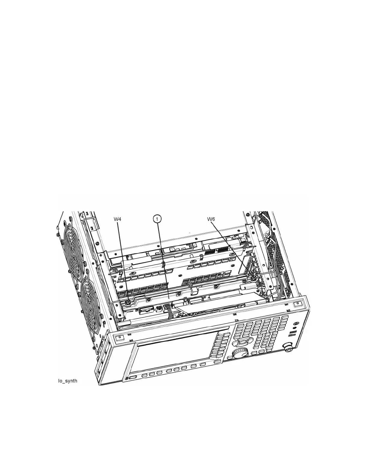
Refer to Figure 5-4. Disconnect cable W4 at A14J740 of the L.O. Synthesizer
Assembly (1).
Figure 5-4 W4 and W6 Location

 Loading...


