Keysight N9010A EXA Service Guide 225
RF Section Troubleshooting (Millimeter-Wave Analyzers)
Troubleshooting
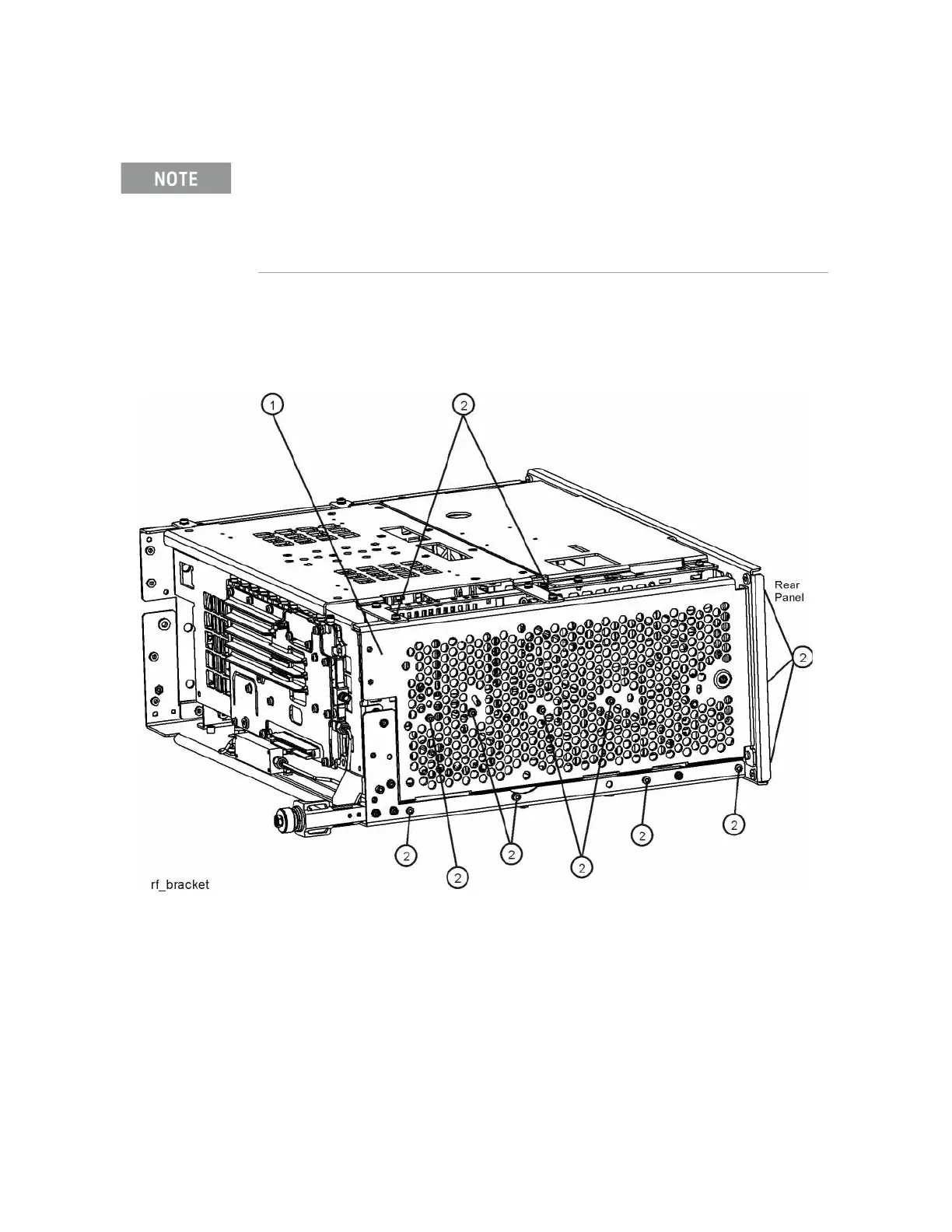
In order to gain access to the front end components, remove the side chassis
(1) by removing the 16 screws (2). See Figure 5-9.
Figure 5-9 Remove the Side Chassis
High Band #2 signal path utilizes a high band mixer internal to the A13 Front End Assembly for
input frequencies from 17.0 GHz to 34.5 GHz. High Band #3 signal path utilizes a high band
mixer internal to the A13 Front End Assembly for input frequencies from 34.4 to 44 GHz. Failures
from 3.6 GHz to 44 GHz will most likely be caused by the A13 RF Front End Assembly. If the
failure is amplitude related, proper adjustments such as frequency response and the YTF
Preselector adjust should be performed first before changing the A13 RF Front End Assembly.

 Loading...


