Keysight N9010A EXA Service Guide 231
RF Section Troubleshooting (Millimeter-Wave Analyzers)
Troubleshooting
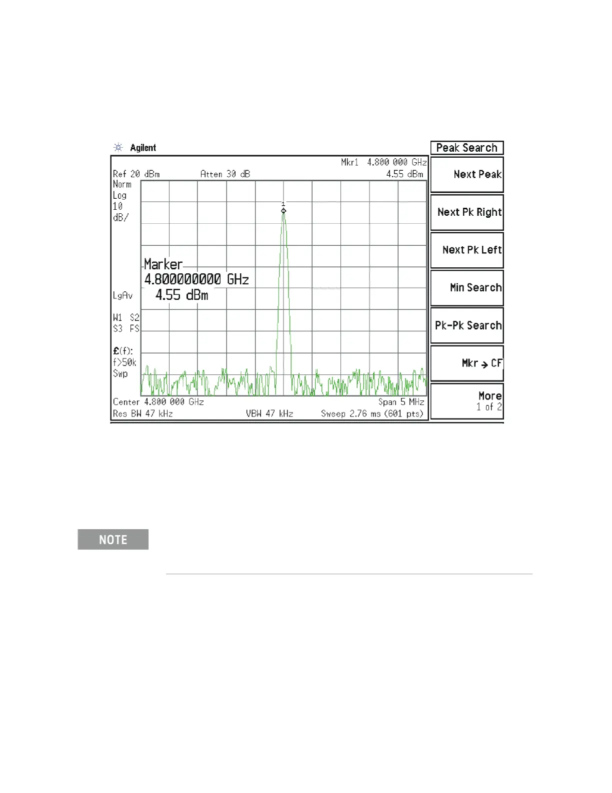
Adjust the functioning spectrum analyzer to measure a signal at 4.8 GHz at
+4.5 dBm ± 2 dB as shown in Figure 5-14.
Figure 5-14 4.8 GHz Signal
If this power level is incorrect, the most probable cause is the A16 Reference
Assembly. If this level is correct and yet the signal previously measured at
A14J740 is incorrect, the most probable cause is the A14 L.O. Synthesizer
Assembly. Reconnect W4 cable to A14J740. Reconnect W6 cable to A14J200.
A13 Front End Assembly Verification
Many portions of the Front End Assembly have been verified earlier in the High
Band troubleshooting process outlined above.
The input signal level was measured on W46 or W7 as part of the A13 Front
End Input Verification.
The output signal level was measured at A13J7 during the quick check to verify
the High Band signal path.
The LO input at A13J4, and the LO outputs were tested when performing the
First LO Verification.
The A13 Front End assembly is shown as A13 and A13A1 for troubleshooting clarification.
However, A13A1 is not separately replaceable. The entire A13 assembly must be replaced which
includes A13A1.

 Loading...


