254 Keysight N9010A EXA Service Guide
Front End Control Troubleshooting
A15 Front End Control Assembly Troubleshooting
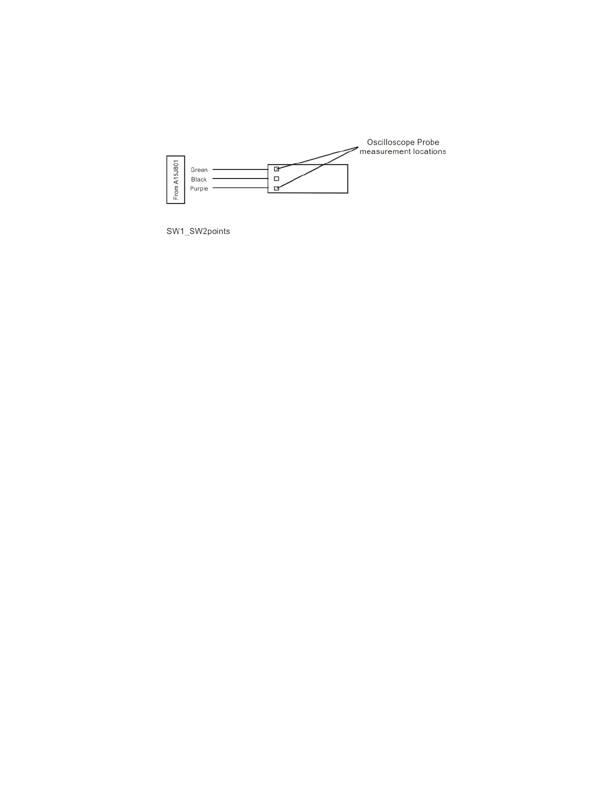
Figure 6-9 Connector Detail
The voltage should be ~21.5 VDC steady state at this point. When you switch
from Standard Path to uW Preselector Bypass, you should see a negative going
pulse to 0 VDC on the oscilloscope for ~15 mS before the voltage returns to
~21.5 VDC steady state. The oscilloscope triggering may need to be adjusted
to see the negative going pulse. This can be tested on both connectors that
contain the green wire.

 Loading...


