Keysight N9010A EXA Service Guide 253
Front End Control Troubleshooting
A15 Front End Control Assembly Troubleshooting
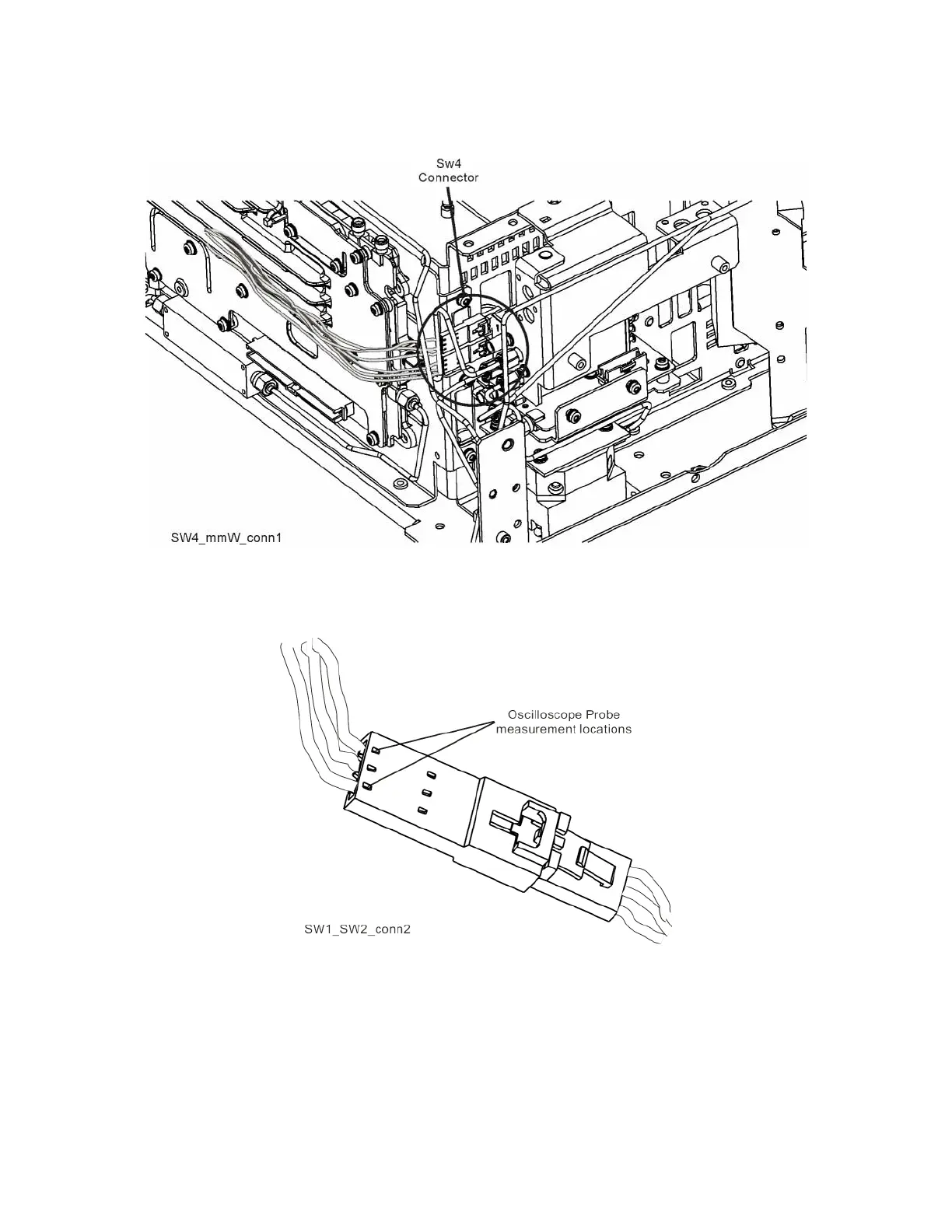
Figure 6-7 SW4 Connector Location (Option 532 and 544)
Figure 6-8 Connector Close-up
To verify the control logic, press Mode Preset on the analyzer. Press FREQ,
5 GHz, SPAN, 1 MHz, AMPTD, More 1 of 2, uW Path Ctrl. Standard Path is
selected by default. Carefully place the scope probe tip on the conductive
portion where the green wire goes into the connector, see Figure 6-9.

 Loading...


