252 Keysight N9010A EXA Service Guide
Front End Control Troubleshooting
A15 Front End Control Assembly Troubleshooting
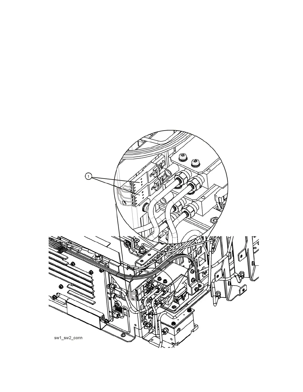
Figure 6-6, Figure 6-7, and Figure 6-8 illustrate the measurement location
where the oscilloscope probe should be used to measure the logic. There are
two connector bodies with three wires each. On one connector, the three wires
are green, black and orange. On the other connector, the three wires are green,
black, and yellow. On each connector, black is ground.
On analyzers with Option 507, 513, and 526, both connectors are used; one
connects to SW1 and the other to SW2. It does not matter which connector
connects to which switch. Both connectors are programmed to behave
identically.
However, on analyzers with Option 532 or 544 only the green, black, yellow
connector is used to control SW4.
Figure 6-6 SW1 and SW2 Connector Location

 Loading...


