Keysight N9010A EXA Service Guide 299
Analog/Digital IF Troubleshooting
40 MHz BW IF Section
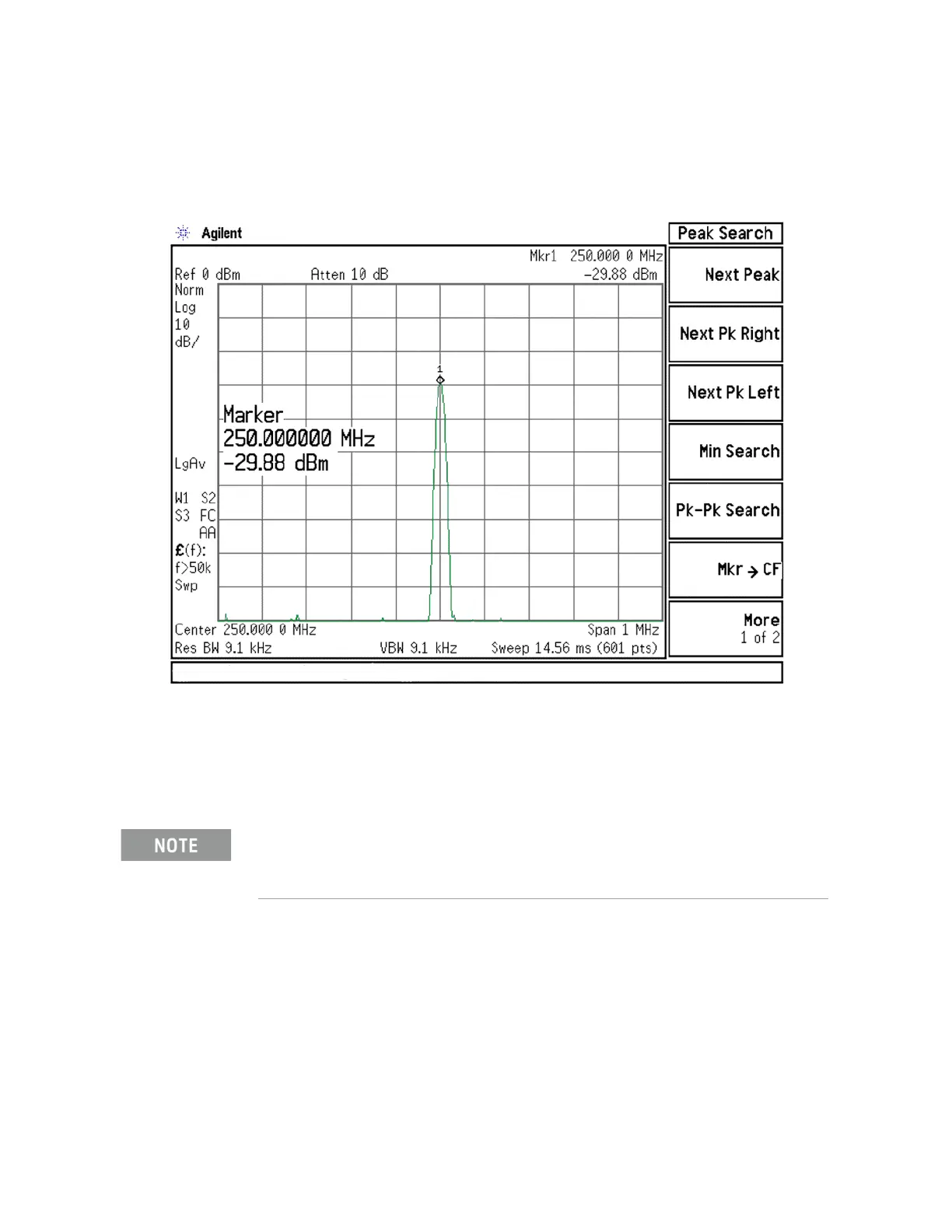
13.The analyzer marker should read 250 MHz at −30 dBm ± 4 dB as shown in
Figure 7-21.
Figure 7-21 250 MHz IF Input
14.If the 250 MHz signal is not measuring the correct power level, see
Chapter 6, “Front End Control Troubleshooting” in this service guide.
15.If the 250 MHz signal is within tolerance, carefully reconnect the W38
cable to A3J15.
You should hear a distinct snap when reconnecting the cable. If this cable is not installed
properly, intermittent signal fluctuations may occur on the analyzer display.

 Loading...


