Keysight N9010A EXA Service Guide 301
Analog/Digital IF Troubleshooting
40 MHz BW IF Section
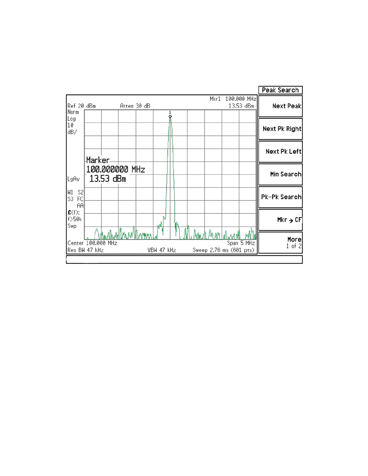
10.The analyzer marker should read 100 MHz at +10 dBm ± 4 dB as shown in
Figure 7-23.
Figure 7-23 100 MHz Reference Input
11.If the 100 MHz signal is measuring incorrectly, see Chapter 8, “L.O.
Synthesizer/Reference Troubleshooting” in this service guide.
12.If the 22.5 MHz IF, 250 MHz IF (if appropriate) and 100 MHz reference
signals measure the correct frequency and amplitude and yet the display
is not processing the signal properly, the most probable causes are the A3
Digital IF or the A4 CPU. It is difficult to separate these two assemblies
given the architecture of the analyzer. Each assembly will have to be tried
to see which one is causing the failure.

 Loading...


