514 Keysight N9010A EXA Service Guide
Assembly Replacement Procedures
RF Area (Option 532, 544)
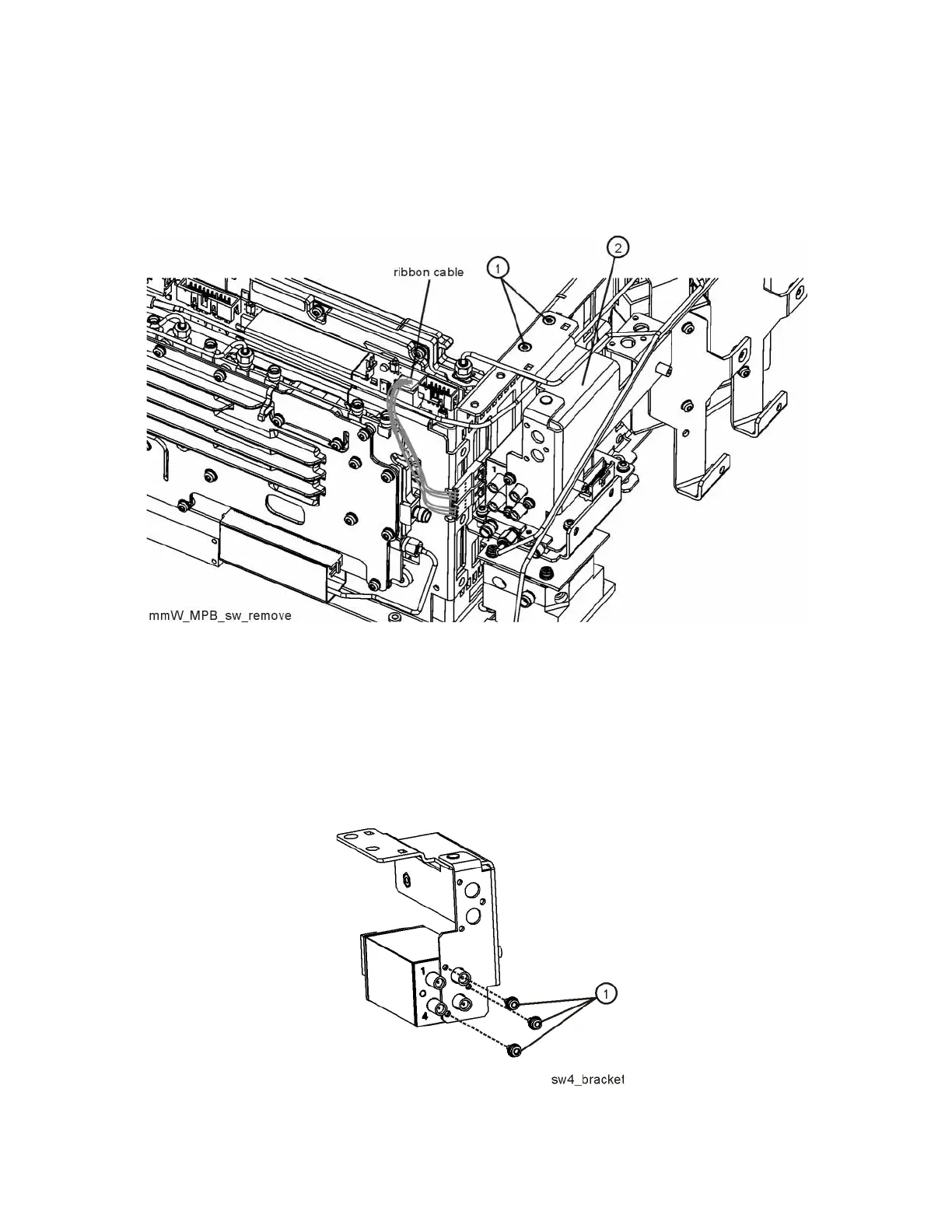
2. Refer to Figure 15-42. Unplug the ribbon cable from the A15 Front End
Control assembly.
Figure 15-42 Remove SW4
3. Remove the two screws (1) that attach the bracket to the chassis. The
bracket/switch (2) can now be removed.
4. Refer to Figure 15-43. Remove the three screws (1) to separate the switch
from the bracket assembly.
Figure 15-43 Switch / Bracket Separation

 Loading...


