Keysight N9010A EXA Service Guide 65
Boot Up and Initialization Troubleshooting
Potential Problems During Boot Process
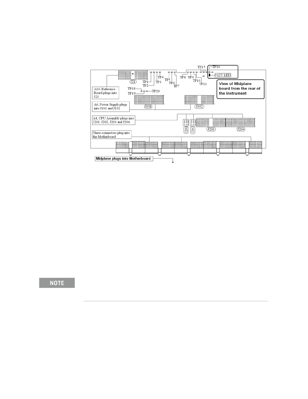
6. Refer to Figure 2-6, verify that the +12D VDC power supply is on.
Figure 2-6 A7 Midplane Board +12D LED
Is the +12D backlight supply voltage LED on?
If yes:
Proceed to step 7.
If no:
Replace the A6 Power Supply assembly.
7. With the instrument turned off remove the 8 screws that attach the front
panel assembly to the instrument chassis.
8. Without disconnecting any of the cables carefully lay the front panel
assembly face down on the work surface.
9. Refer to Figure 2-7, verify the 3 voltage levels listed in Table 2-1 are
correct.
The instrument does have a screen saver which can disable the display backlight after a
predefined period of time. If there is any question as to whether or not this has been set by the
user prior to the current failure, and the “Inverter Enable” voltage measures too low, press a
front panel key and see if the voltage level increases to the expected level.

 Loading...


