DIODE BOARD - DB1
The diode board (16, Figure 3-3) contains replaceable
diodes. Some of the diodes are used in the coil circuit
of various relays to suppress the resultant coil voltage
spike when power is removed from the circuit, prevent-
ing damage to other circuit components (lamp fila-
ments etc.). Other diodes are used to control the flow
of current in a circuit as required. Resistors or diodes
may also be installed in sockets P7 through P12 (3,
Figure 3-5). Refer to the schematics in Section “R” for
specific circuits.
Diode board, DB1 contains 24 replaceable diodes. The
diodes are mounted on a plug-in connector for easy
replacement.
Diode Testing
Refer to the electrical schematic in Section R of this
manual for the specific circuit and diode to be tested.
If a diode failure is suspected, remove and check the
diode as follows:
1. Grasp the diode connector, compressing the lock-
ing “ears” while pulling the connector off the
board. Note the connector “key” used to ensure
correct polarity.
NOTE: Some digital multimeters are designed to test
diodes. If this type is used, follow the manufacturer’s
instructions for proper test.
2. An analog ohmmeter can be used to test the diode
as follows:
a. Place the meter on the “X100” scale.
b. With the red meter lead (+ ) on the banded end
of the diode and the black lead (-) on the other
diode lead, the meter should read between
1000 and 2000 ohms.
c. Reverse the meter leads and read infinite resis-
tance.
3. If no resistance is read on the meter, the diode is
open and must be replaced.
4. If the meter reads zero ohms, the diode is shorted
and must be replaced.
5. Orient the diode assembly for proper polarity
(“key” noted in step 1.) and insert connector until
locked in position on mating receptacle.
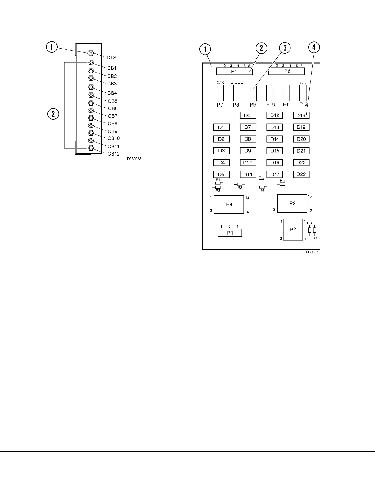
FIGURE 3-4. CIRCUIT BREAKER PANEL
1. Cabinet Service Light Switch
2. Circuit Breakers
FIGURE 3-5. DIODE BOARD 1
1. Diode Board 1 (DB1)
2. Connectors (P1 - P6)
3. Sockets (P7 - P12)
4. Diodes (D1 - D23)
D3-8 24VDC System Components D03019 04/01