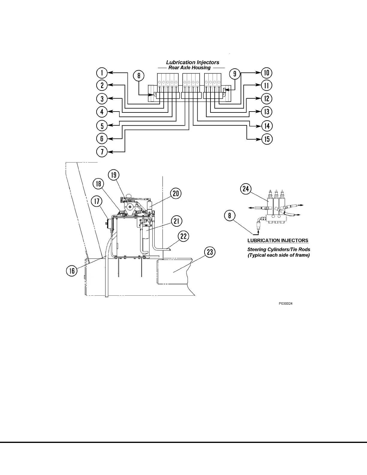
FIGURE 3-2. AUTO LUBE SYSTEM INSTALLATION
1. L.H. Suspension, Top Bearing
2. L.H. Suspension, Bottom Bearing
3. L.H. Body Pivot Pin
4. L.H. Hoist Cylinder, Top Bearing
5. L.H. Hoist Cylinder, Bottom Bearing
6. L.H. Anti-Sway Bar Bearing
7. Rear Axle Pivot Pin
8. Grease Supply From Pump
9. Pressure Switch, N.O., 2000 psi (13 790 kPa)
10. R.H. Suspension, Top Bearing
11. R.H. Suspension, Bottom Bearing
12. R.H. Body Pivot Pin
13. R.H. Hoist Cylinder, Top Bearing
14. R.H. Hoist Cylinder, Bottom Bearing
15. R.H. Anti-Sway Bar Bearing
16. Vent Hose
17. Junction Box
18. Pressure Switch, N.O., 2500 psi (17 237 kPa)
19. Grease Pump
20. Vent Valve
21. Filter
22. Grease Supply to Injectors
23. Truck Frame
24. Injector
NOTE: The above illustration shows the standard location for the lube pump & reservoir (right
platform). This assembly may be located on left platform on some models.
P3- 2 Automatic Lubrication System P03018 4/00