FRONT BEARING REMOVAL
1. Remove retaining ring (1, Figure 13-23) from front
outer side of front housing.
2. Remove retaining ring (3, Figure 13-23) from rear
inner side of front housing.
3. Support front housing on blocks and with a press,
remove front bearing (4, Figure 13-23) from front
housing. Use Tool BF4818 (Figure 13-24).
FRONT ROTOR REMOVAL
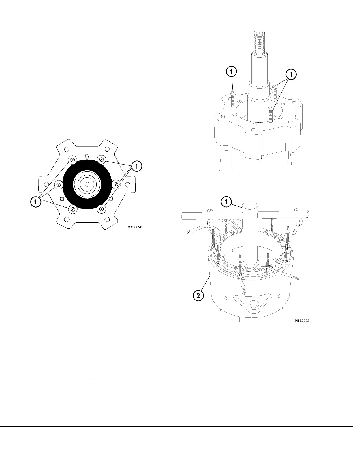
1. Remove six flanged locknuts from core studs or
six self tapping screws (Figure 13-16).
2a. Use three 10-32 UNF x 2” long machine screws
as Jacks in the three threaded holes of rotor end
plate (Figure 13-17). Pull rotor off core gradually
by working screws against core in sequence.
Alternate Method
2b. Using an air hammer (air chisel) with a blunt
tipped tool, vibrate the area around the rotor
element to rotor core attaching studs. The vibra-
tions should loosen the built up rust in that area.
Remove the rotor element. If resistance is still felt,
use the method described in “2a.” above, plus the
air hammer.
FIELD COIL REMOVAL
Do not attempt to repair field coil.
Replace the whole assembly.
1. Mark the position of field coil leads (white wires
with spade terminals) on stator. New fields will be
positioned in same opening in stator assembly,
as the old field leads.
2. Remove the screws attaching field coil bobbin to
stator tabs (Figure 13-18).
3. Use tool BF4820 to rotate field coil bobbin about
20 degrees to disengage bobbin ears from stator
tabs.
Note: Some force may be required to break the perma-
fill coating on the tabs.
FIGURE 13-16.
1. Flanged Locknuts or Screws
FIGURE 13-17.
1. Jack Screws
FIGURE 13-18.
1. Bobbin Removal Tool 2. Stator & Shell Assembly
(BF4820)
M13-16 Niehoff Alternator Overhaul Manual M13003 04/01