PAYLOAD METER II
ON BOARD WEIGHING SYSTEM (OBWS)
GENERAL INFORMATION
The Payload Meter II On Board Weighing System
displays and records the payload weight along with
other operating information. The system consists of a
payload meter, pressure sensors, deck mounted lights
and an inclinometer.
The payload meter (Figure 20-1) uses the four suspen-
sion pressures and an inclinometer to determine the
load in the truck. The payload weight can be displayed
in short tons or metric tons.
There are three external deck-mounted lights on each
side of the truck. The lights indicate payload weight
divided into three separate stages. A forecast feature
will flash a deck mounted light predicting the payload
weight if the next bucket of material is dropped into the
body.
The payload meter stores in memory various operating
data. This data includes:
1) The payload, time, distance, and travel speed for
each cycle.
2) The date and time that the engine was started and
stopped.
3) The date and time of each fault that occurred or
was canceled.
4) The total payload and the overall number of cycles
for a specific time period.
This data is retained even when the power is switched
off. The stored data is backed up by an internal battery.
The data can be down loaded from the payload meter
to a personal computer when a communication cable
is connected to the port inside the cab.
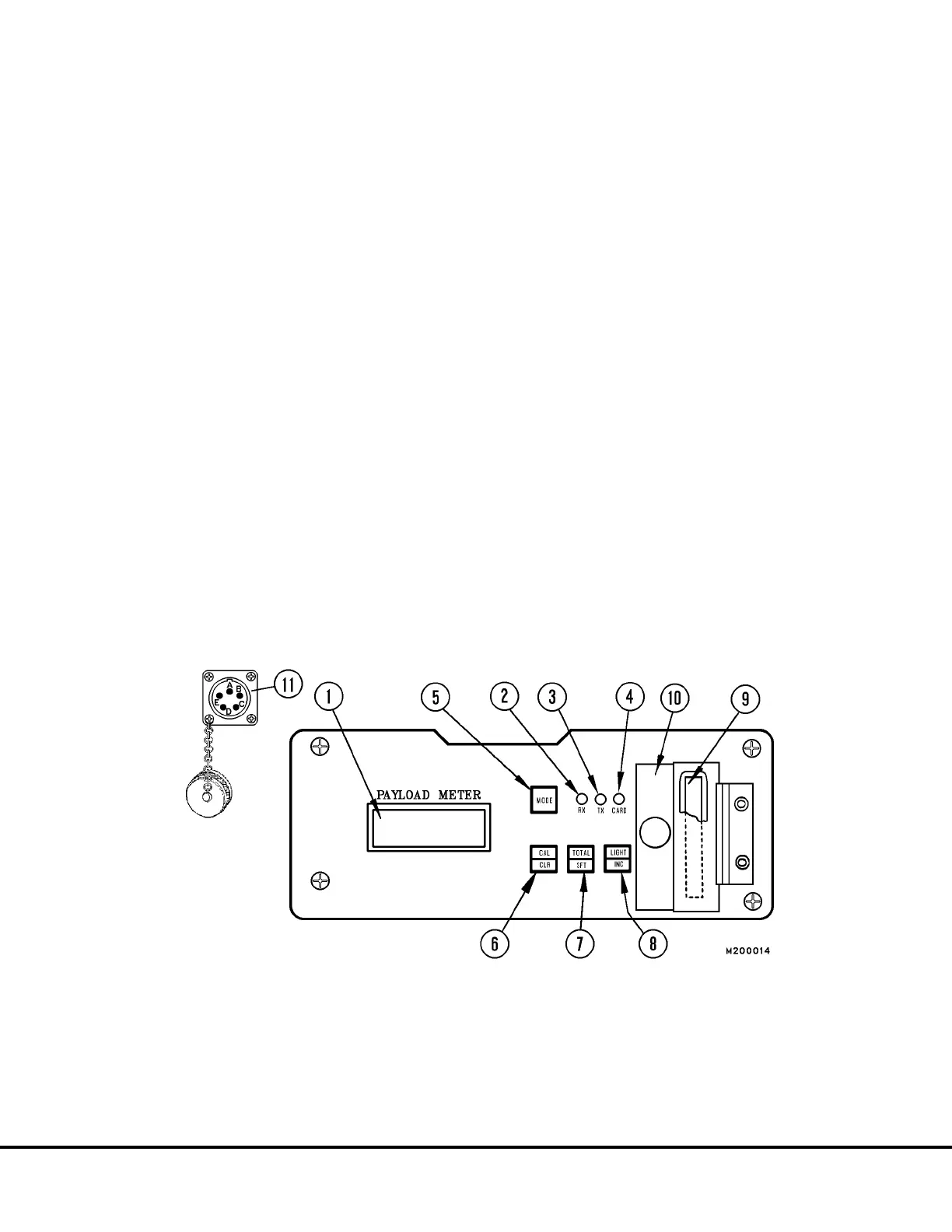
FIGURE 20-1. PAYLOAD METER II
1. Display panel 7. Total/shift switch [TOTAL] [SFT]
2. Reception pilot lamp (Rx busy) 8. Light/increment switch [LIGHT] [INC]
3. Transmission pilot lamp (Tx busy) 9. Memory card
4. Memory card access lamp (CARD busy) 10. Cover
5. Mode switch [MODE] 11. Diagnostic/Download Port
6. Calibration/clear switch [CAL] [CLR]
WARNING - When not inserting or removing memory card (9), always keep the cover (10) closed)
M20007 10/00 Payload Meter II M20-3