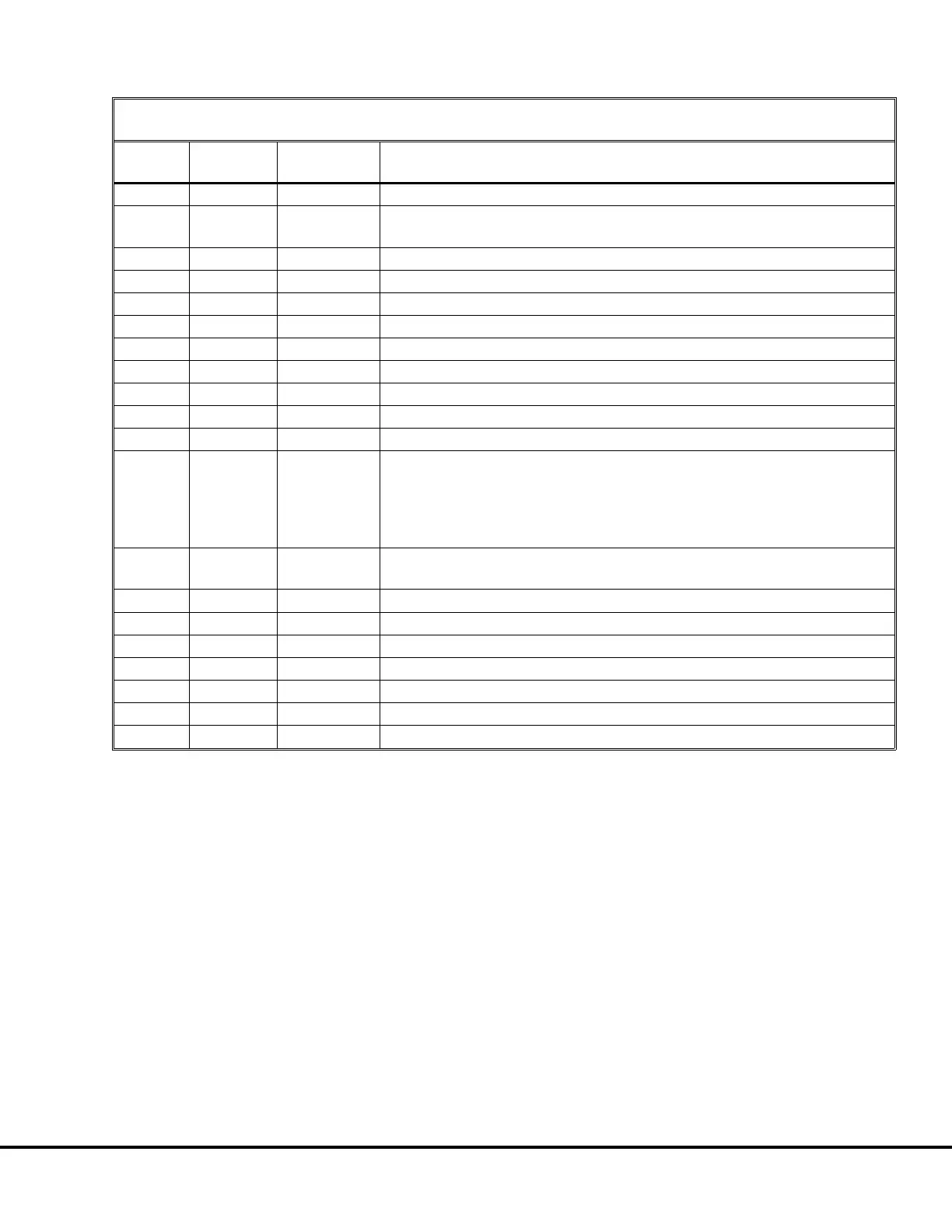
TABLE I. CIRCUIT RESISTANCE CHECKS
(All readings taken from circuit to ground)
CIRCUIT LOCATION
APPROX.
VALUE
NOTES
11B1
*
∞
*Measure at the 12VDC insulator in the Electrical Interface Cabinet.
11
*
∞
*Measure at the 24VDC insulator in the Electrical Interface Cabinet.
All devices listed for 11A circuit reading must be OFF.
15V
TB21
∞
71GE
TB22
120Ω
71TCI
TB23
120Ω
17FL349 Panel Only (Not applicable on 17FL373 Panel.)
439
TB25
∞
10V
TB28
∞
11SL
TB28
∞
Engine service lights turned OFF.
11ST
TB28
∞
15PV
TB29
∞
11S
TB30
∞
Ground level engine shutdown switch open
11A
TB30
∞
The following must be turned OFF:
Brake cabinet service light, operator cab light, passenger seat
compartment service light, hazard lights, headlights, ground level engine
shutdown switch, engine governor heater switch (MTU 396 only - in
Electrical Interface Cabinet), left and right side engine service lights.
11T
TB30
>36Ω
Engine governor heater switch in Electrical Interface Cabinet open.
(MTU 396 engine only)
11FR
TB30
∞
(MTU 396 engine only)
11HTR
TB30
∞
(MTU 396 engine only)
712
TB32
∞
The Electrical Interface Cabinet service lights must be switched OFF.
71
TB32
∞
11L
CB30
∞
Measure at circuit breaker CB30 in cab.
12M
*
>10Ω
*Measure at AID Module terminal B-13 under passenger seat in cab.
12F
*
>200Ω
*Measure at AID Module terminal B-12 under passenger seat in cab.
E03015 3/01 AC Drive System Electrical Checkout Procedure E3-5
(Release 17 Software)