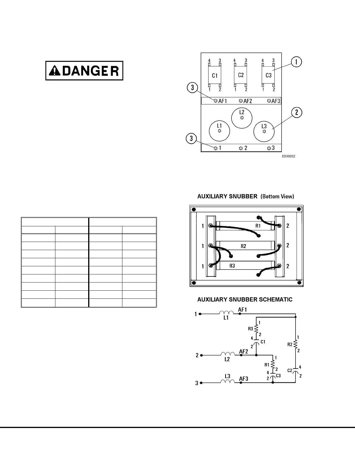
Auxiliary Snubber Panel
Troubleshooting
The Auxiliary Capacitor Panel remains charged for
at least 15 minutes after engine shutdown. Be
certain LED’s D1 and D2 (6, Figure 3-12) are OFF
before working on Auxiliary Blower Control cir-
cuits.
1. After verifying capacitor charge warning LED’s (6,
Figure 3-12) are not lit, disconnect external wiring
from snubber panel terminals (3, Figure 3-10) to
isolate the panel from other system components
before making measurements.
2. Using an ohmmeter and capacitance meter, verify
Snubber Panel components by measuring resis-
tance values between points shown in Table be-
low. Refer to Figure 3-10 and 3-11 for test point
locations.
3. After all measurements have been made and
repairs completed if needed, reconnect wiring
removed in step 1.
Measuring Point Specified Value
From To Minimum Maximum
1 C2-4
23.75 Ω 26.25 Ω
1 C1-4
23.75 Ω 26.25 Ω
2 C3-4
23.75 Ω 26.25 Ω
3 C2-2
0 Ω 0 Ω
C1-2 R1-1
0 Ω 0 Ω
3 C3-2
0 Ω 0 Ω
C1-4 C1-2
0.10 µF 0.17 µF
C2-4 C2-2
0.10 µF 0.17 µF
C3-4 C3-2
0.10 µF 0.17 µF
FIGURE 3-16. AUXILIARY SNUBBER PANEL
1. Capacitor
2. Choke
3. Terminals
FIGURE 3-17. AUXILIARY SNUBBER SCHEMATIC
E3-42 AC Drive System Electrical Checkout Procedure 3/01 E03015
(Release 17 Software)