RIM
Tire Removal
DO NOT weld or apply heat on the rim assembly
with the tire mounted on the rim. Resulting gases
inside the tire may ignite causing explosion of tire.
When inflating tires always use a safety cage.
Never inflate a tire until the lockring is securely in
place. Do not stand in front of or over the lockring
during inflation procedures. Never overinflate a
tire. Refer to tire manufacturers recommenda-
tions.
1. Place tire and wheel assembly in safety cage and
discharge all air pressure from tire.
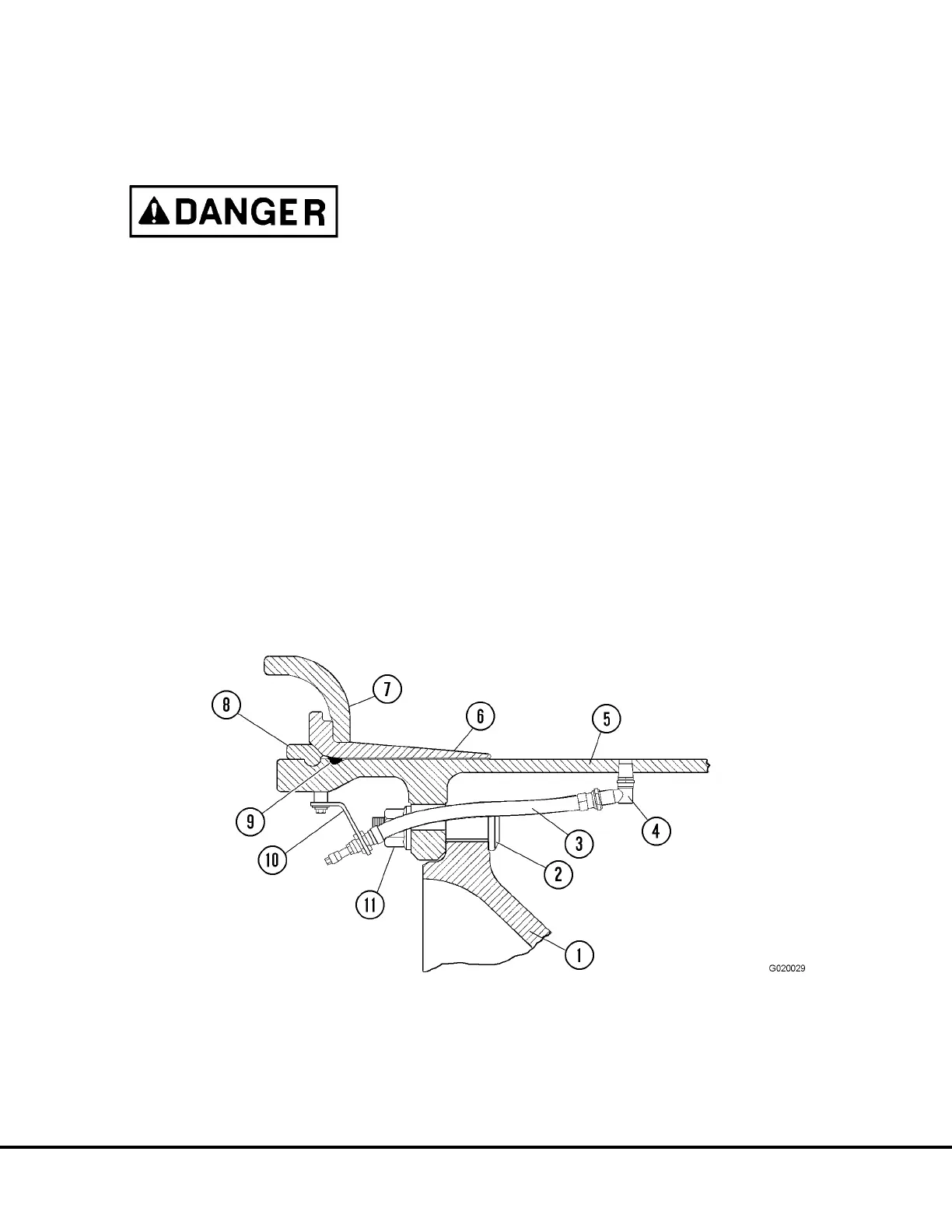
2. Attach a hydraulic bead breaker to the rim by
slipping the jaws of frame assembly over the outer
edge of flange (7, Figure 2-6). Make sure the jaws
of the frame are as near to the bead seat band (6)
as possible.
3. Following tool manufacturers instructions, move
tire bead in far enough to permit placing a wedge
between tire and flange at side of tool.
4. Repeat this procedure at locations approximately
90° from the first application. Continue this pro-
cedure until tire bead is free from rim.
5. After bead is broken loose, insert flat of tire tool in
beading notch on lockring (8). Pry lockring up and
out of groove on rim.
6. Pry in on bead seat band (6) until O-ring (9) is
exposed. Remove O-ring.
7. Remove bead seat band (6) from rim (5) and
remove flange (7).
8. Reposition wheel assembly and repeat removal
procedure on opposite side of tire. Remove tire
from rim.
FIGURE 2-6. FRONT WHEEL HUB AND RIM ASSEMBLY
1. Wheel Hub
2. Stud
3. Tire Inflation Hose
4. Swivel Connector
5. Rim
6. Bead Seat Band
7. Side Flange
8. Lock Ring
9. O-Ring
10. Clamp Bracket
11. Flanged Nut
G2-6 Tires and Rims G02015