Hoist Counterbalance Valve Adjustment
Preparation:
1. With the engine shut down, the body resting on
the frame, the hoist valve in the FLOAT position
and hydraulic system pressure bled down,
loosen locknut on adjustment stem of needle
valve (3, FIGURE 10-8) on overcenter manifold
(6). Turn adjustment stem fully clockwise.
2. Remove plug from “PILOT VENT” port (4) on
overcenter manifold. This port will remain open
to atmosphere during adjustment; do not allow
dirt to enter open port.
Note: It is suggested a clean SAE #4 (1/4") hydraulic
hose is installed in the open port and the hose pointed
downward.
3. Install a 5000 psi (35,000 kPa) gauge at test port
“TR” on overcenter manifold. (Gauge will meas-
ure rod end pressure; the pressure controlled by
the counterbalance valve.)
Counterbalance Valve Pressure Check Only:
1. Start the engine. At low idle, raise the body and
as it extends to the third stage, read the pressure
on the gauge connected to the “TR” port. (All
counterbalance valve pressures are read/ad-
justed while hoist cylinders are in third stage.)
a. If pressure is 3000 psi (20.7 MPa) or above,
stop hoisting immediately.
Pressure is adjusted too high and must be
lowered. Go to “Counterbalance Valve Ad-
justment” and perform adjustment procedure.
b. If pressure is below 3000 psi (20.7 MPa),
increase engine speed by approximately 300
rpm and observe pressure on gauge.
1.) If pressure is still below 3000 psi (20.7 MPa),
continue increasing engine speed in steps of
300 rpm, while in third stage and observing
pressure gauge.
2.) Continue monitoring pressure gauge until
engine high idle is attained.
c. If gauge indicates 3000 psi (20.7 MPa) while
at high idle, in POWER UP and in third stage,
counterbalance valve adjustment is correct.
d. If gauge does not indicate 3000 psi (20.7 MPa)
while in third stage and at high idle (or a lesser
rpm during step 1b, 1.) perform “Counterbal-
ance Valve Adjustment” procedure.
Counterbalance Valve Adjustment
1. Loosen locknut on adjustment stem of counter-
balance valve (2, FIGURE 10-8) (Labeled “CBV”
on manifold). Turn adjustment stem fully clock-
wise to start adjustment procedure so counter-
balance valve pressure is as low as possible.
Note: Turning adjustment stem in (clockwise) de-
creases the pressure. Turning the stem out (counter-
clockwise) increases the pressure.
Complete valve
adjustment range is 3 turns.
2. Start the engine and operate at high idle. Raise
the body while observing the pressure gauge.
Slowly adjust counterbalance valve to obtain
3000 psi (20.7 MPa) as the hoist cylinder 3rd
stage extends while in POWER UP. When
adjustment is complete, secure locknut on
adjustment stem.
3. Repeat Counterbalance Valve Pressure Check,
step 1. to verify proper adjustment.
* Record on Data Sheet
4. Replace plug in “PILOT VENT” port. Remove
pressure gauge.
5. Turn needle valve adjustment stem fully out and
secure locknut.
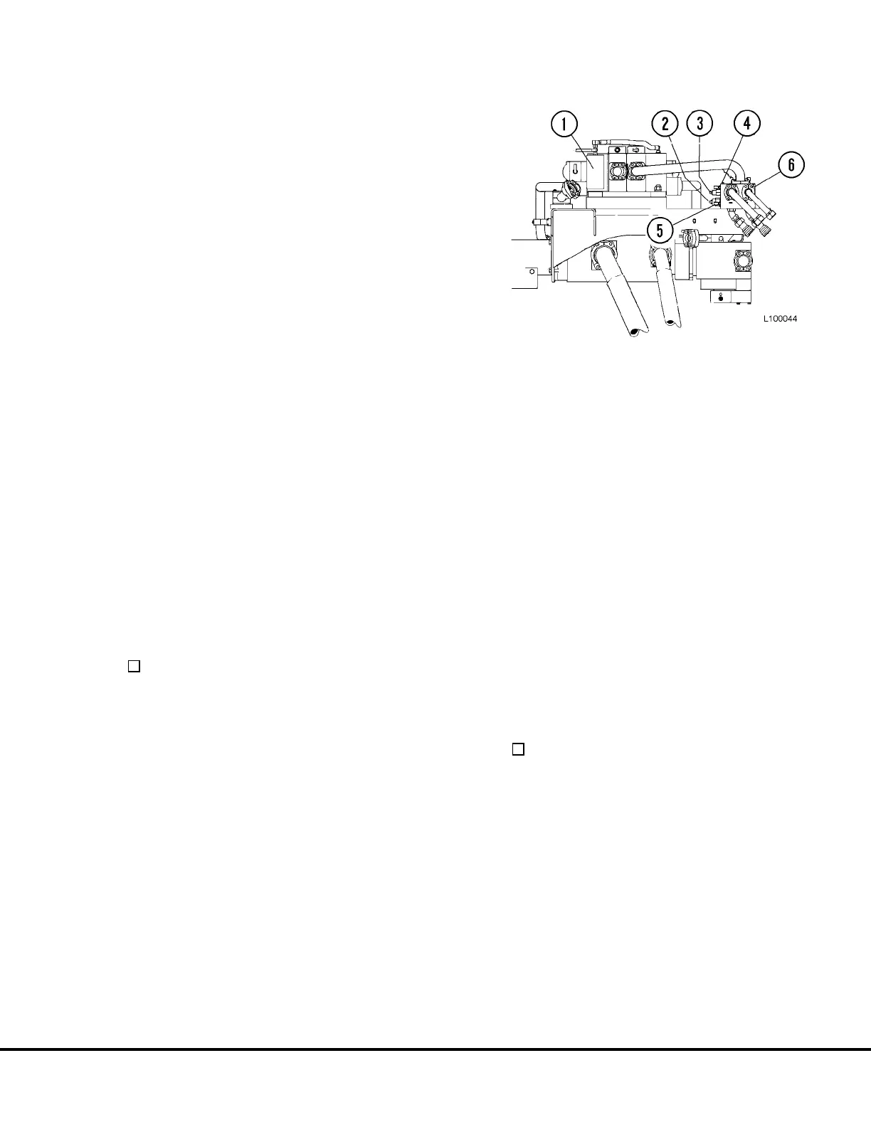
FIGURE 10-8. COUNTERBALANCE VALVE
ADJUSTMENT
1. Hoist Valve
2. Counterbalance Valve
3. Needle Valve
4. “Pilot Vent” Port Plug
5. “TPD” Pressure Test Port
6. Overcenter Manifold
L10012 Hydraulic Check-out Procedure L10-9