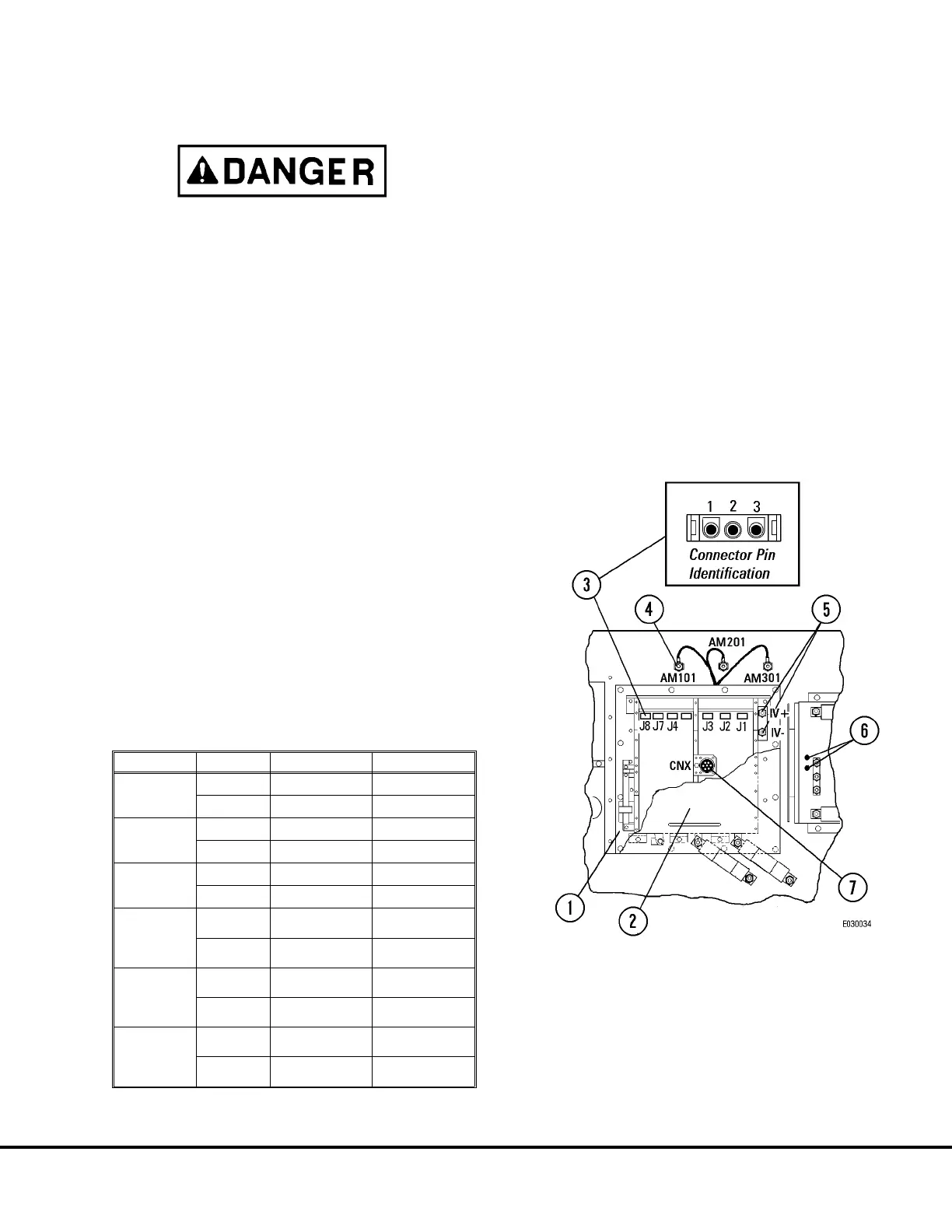
IGBT Troubleshooting
The Auxiliary Capacitor Panel remains charged for
at least 15 minutes after engine shutdown. Be
certain LED’s D1 and D2 (6, Figure 3-12) are OFF
before working on Auxiliary Blower Control cir-
cuits.
1. After verifying capacitor charge warning LED’s (6,
Figure 3-12) are not lit, remove cable attached at
CNX connector (7).
2. Remove 6 screws retaining cover (2). Remove
cover.
3. Disconnect cables at AM101, AM201, and AM301
connection studs (4) and isolate from other cir-
cuits.
4. Disconnect wires at IV+ and IV- terminals (5).
5. Remove connectors J1, J2, J3, J4, J7 and J8.
Refer to Figure 3-12 for pin numbers when view-
ing face of harness end of connector.
6. Using an ohmmeter and the specifications in the
Table below, measure by probing the pins in the
harness connectors. All circuit test points listed in
the Table should show continuity.
Note: All #3 pins in connectors should show an open
circuit to all other test points.
All IGBT’s should be free of cracks or leaks.
7. After all circuits have been tested, reconnect all
cables to their proper terminals. Reconnect J1,
J2, J3, J4, J7 and J8.
8. Reinstall cover (2) and attach harness connector
at CNX receptacle.
Connector From Pin To Measurement
J1
1
IV+ Continuity
2
AM101 Continuity
J2
1
AM101 Continuity
2
IV- Continuity
J3
1
IV+ Continuity
2
AM201 Continuity
J4
1
AM201
Continuity
2
IV-
Continuity
J7
1
IV+
Continuity
2
AM301
Continuity
J8
1
AM301
Continuity
2
IV-
Continuity
FIGURE 3-18. IGBT CHECK TEST POINTS
1. Auxiliary Inverter
(Controller)
2. Cover
3. 3-Pin Connectors
4. AM101, AM201, AM301
Connection Studs
5. IV+, IV- Terminals
6. Blower Control System
Warning LED’s
7. CNX Connector
E03015 3/01 AC Drive System Electrical Checkout Procedure E3-43
(Release 17 Software)