Power Module Removal
Recheck to be certain all hoses, electrical cables,
ground straps etc. have been removed.
1. Remove capscrews, nuts and washers (8, Figure
2-5) securing front subframe support to main
frame.
Install safety chain around the engine subframe
cross member and main frame to prevent the
power module from rolling when the subframe
rollers are installed.
2. Remove capscrews and caps securing subframe
mounting bushings to the subframe support
bracket (3) at rear of subframe.
3. Check engine and alternator to make sure all
cables, wires, hoses, tubing and linkages have
been disconnected.
Lift power module only at the lifting points on
subframe and engine/alternator cradle structure.
(Refer to Figure 2-5 and 2-7.)
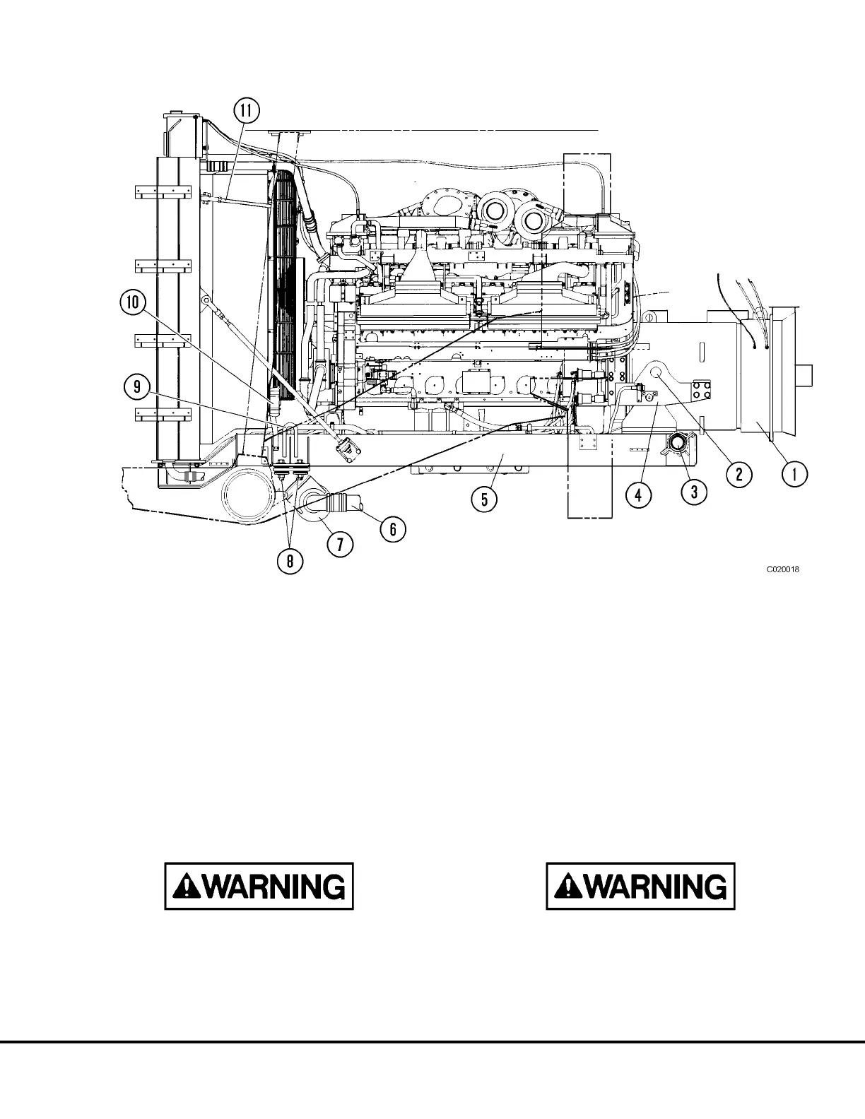
FIGURE 2-5. POWER MODULE REMOVAL & INSTALLATION
1. Alternator
2. Rear Power Module Lift Eye
3. Rear Frame/Sub-frame Mount
4. Engine/Alternator Cradle Structure
5. Power Module Sub-frame
6. Heat Exchanger Piping
7. Heat Exchanger
8. Front Frame/Sub-frame Mount
9. Front Power Module Lift Eye
10. Receiver/Drier
11. Upper Radiator Support Rod
C02017 03/01 Power Module C2-5