HYDRAULIC SYSTEM COMPONENT REPAIR
HOIST PUMP
Removal
NOTE: The hoist pump can be removed without re-
moving the steering pump from the truck if desired.
1. Turn keyswitch “Off” and allow ample time (ap-
proximately 90 seconds) for the accumulators to
bleed down.
2. If necessary, drain the hydraulic tank by use of the
drain valve located on the rear side of the tank.
NOTE: If oil in the hydraulic tank has not been contami-
nated, the shut-off valves can be closed and both
pump inlet lines can be drained, eliminating the need
to completely drain the tank.
3. Remove the rear axle blower duct to allow the hoist
pump to be lowered from the pump module
mounting bracket for removal. Remove duct sup-
port bracket.
4. Close the pump supply shut-off valves.
Always maintain complete cleanliness when open-
ing any hydraulic connection. Insure that all sys-
tem lines and components are capped while the
component is removed from the truck.
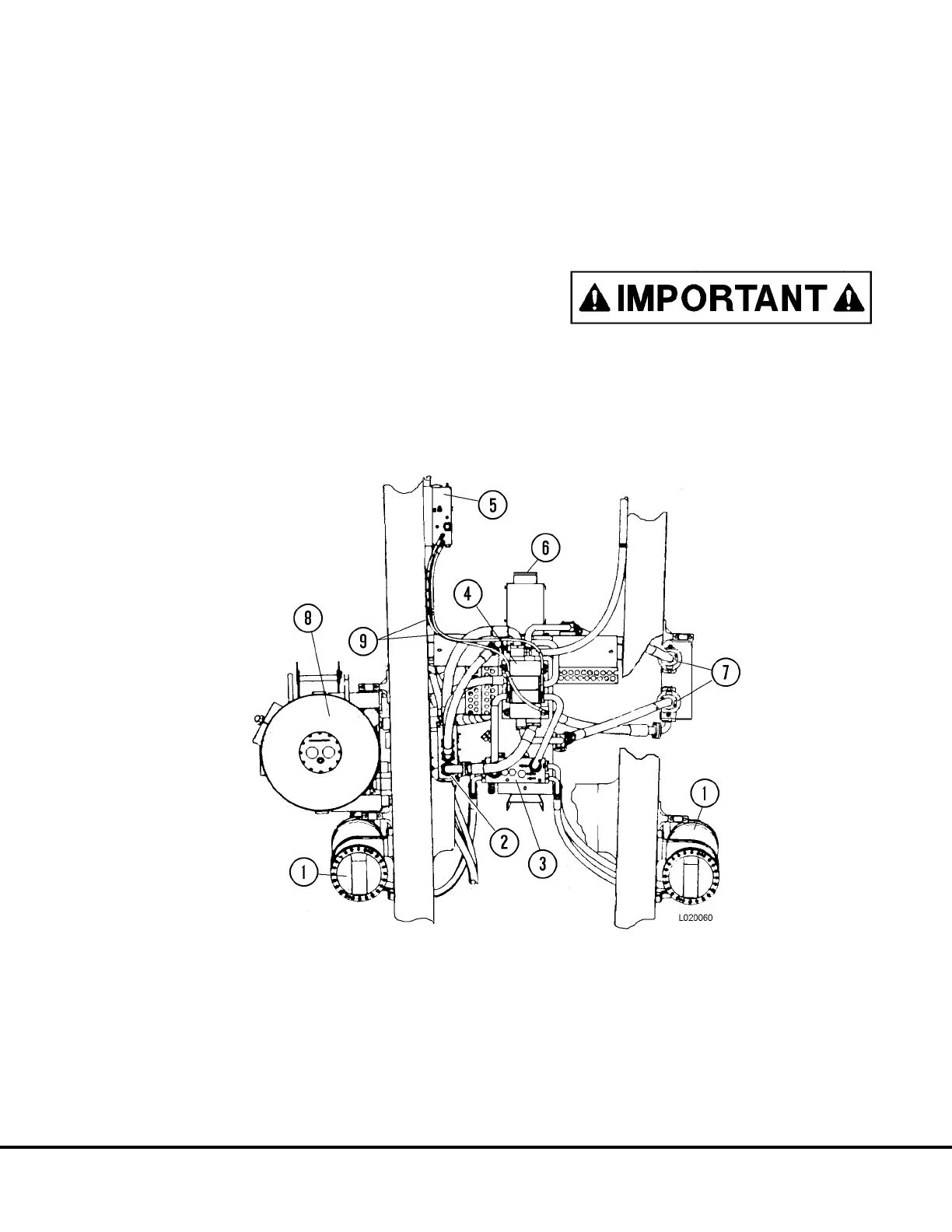
FIGURE 3-1. HOIST AND STEERING PUMP PIPING (Top View)
1. Hoist Cylinders
2. Brake/Hoist Return Oil Manifold
3. Overcenter Manifold
4. Hoist Valve
5. Bleeddown Manifold
6. Pump Driveshaft
7. Hoist Circuit Filters
8. Hydraulic Tank
9. Hoist Valve Pilot Circuit Hoses
L03027 Hydraulic Component Repair L3-1