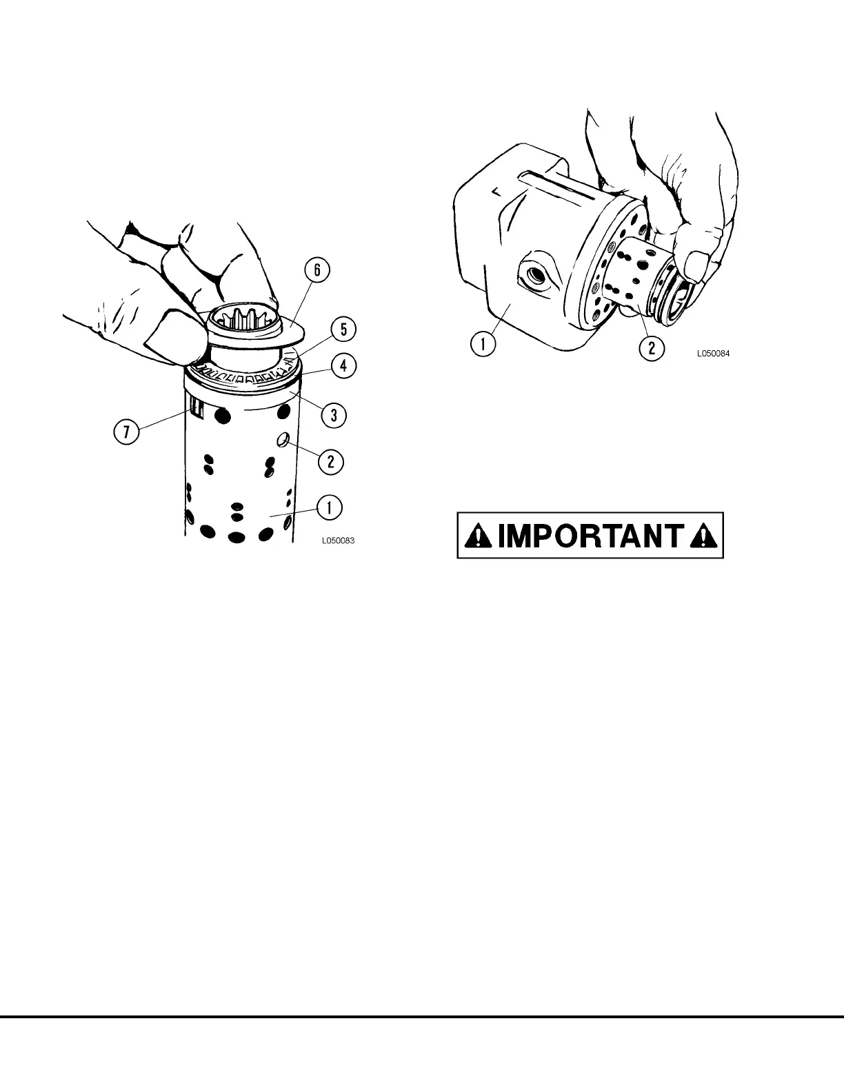
6. With neutral position springs (7, Figure 5-10)
centered in spool and sleeve, install ring (3), rear
bearing race (4), thrust bearing (5) and front
bearing race (6) in that order. The chamfer on the
rear bearing must be facing away from the bear-
ing
7. Place the dust seal (1, Figure 5-7) in position.
Using a flat iron block over the seal, tap into
position.
8. Position the O-ring and kin ring on the spool.
9. Position the steering unit with the housing hori-
zontal. Slowly guide the (lubricated) spool and
sleeve with fitted parts, into the bore using light
turning movements. Refer to Figure 5-11.
NOTE: Cross pin must remain horizontal when spool
and sleeve are pushed into bore to prevent pin from
dropping out of spool.
FIGURE 5-10. BEARING INSTALLATION
1. Sleeve
2. Cross Pin
3. Ring
4. Bearing Race
(with chamfer)
5. Thrust Bearing
6. Bearing race
7. Neutral Position
Springs
FIGURE 5-11. SPOOL INSTALLATION
1. Housing 2. Spool Assembly
L5-6 Steering Control Unit L05021