HOIST SYSTEM RELIEF VALVE AND
BRAKE COOLING CIRCUIT PRESSURES
NOTE: If relief valve or hoist valve assembly has been
replaced or rebuilt, hoist valve “power up” pressure
should be checked. Also, check the brake cooling
circuit for correct pressures.
Check hoist system “power down” relief pressure if the
hoist pilot valve has been replaced or rebuilt.
Relieve pressure before disconnecting hydraulic
lines. Tighten all connections securely before ap-
plying pressure.
Equipment Requirements
The following equipment will be necessary to properly
check-out the hoist relief and brake cooling circuit
pressures:
• Hydraulic schematics, refer to Section “R”.
• Three 0-3500 psi (0-25,000 kPa) range cali-
brated pressure gauges and hoses for hoist
circuit pressure readings.
• Two 0-100 psi (0-1000 kPa) low pressure
gauges and hoses for brake cooling circuit
pressure readings.
Hydraulic oil temperature should be approximately
70°F (21°C) during test.
Pressure Checks
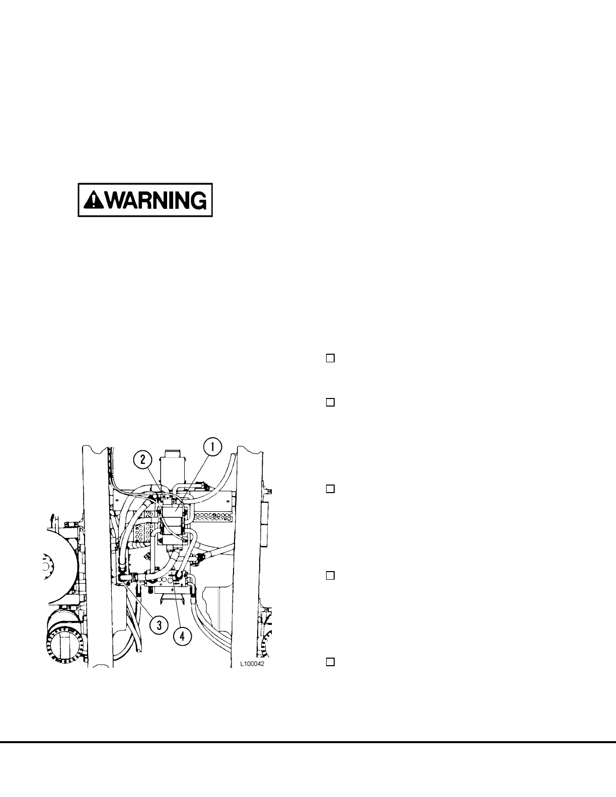
1. Install a 0-100 psi (0-1000 kPa) low pressure
gauge at the brake cooling circuit manifold block
(2, Figure 10-4) at the front of the hoist valve (1)
to monitor front brake cooling oil pressure.
2. Install a 0-3500 PSI (0-25,000 kPa) gauge in the
overcenter manifold (4) power down test port
marked “TPD” located on front face of manifold.
3. Install a 0-3500 PSI (0-25,000 kPa) gauge in each
hoist pump filter pressure test port.
4. Install a 0-100 psi (0-1000 kPa) low pressure
gauge at the upper left test port in the brake/hoist
return manifold (3) to monitor rear brake cooling
supply pressure.
Brake Cooling Circuit Test
1. Start engine and run at low idle. Place hoist
control lever in the FLOAT position.
Hoist pump outlet pressures at the filters
should be approximately 80 psi (550 kPa).
* Record on Data Sheet
Pressure at front and rear brake cooling cir-
cuits (3 & 4, Figure 10-7) should be approxi-
mately 25 psi (172 kPa) or less.
* Record on Data Sheet
2. With engine at low idle, move the hoist control
lever to POWER UP.
Pressure at front and rear brake cooling cir-
cuits (3 & 4) should drop to 0 psi (0 kPa)
while body raises.
* Record on Data Sheet
3. Increase engine speed to 1500 RPM. Place hoist
control lever in HOLD or FLOAT.
Pressure at front and rear brake cooling cir-
cuits (3 & 4) should be approximately 50 psi
(344 kPa) or less.
* Record on Data Sheet
4. With engine at 1500 RPM, move the hoist control
lever to POWER UP.
Pressure at front and rear brake cooling cir-
cuits (3 & 4) should drop to 0 psi (0 kPa)
while body raises.
* Record on Data Sheet
FIGURE 10-4. PUMP PRESSURE TAPS
1. Hoist Valve
2. Front Brake Cooling
Supply
3. Brake/Hoist Return Manifold
4. Overcenter Manifold
L10-6 Hydraulic Check-out Procedure L10012