END HOUSING REMOVAL
1. Remove nine flanged locknuts from stator-tube
assembly studs at rear of end housing.
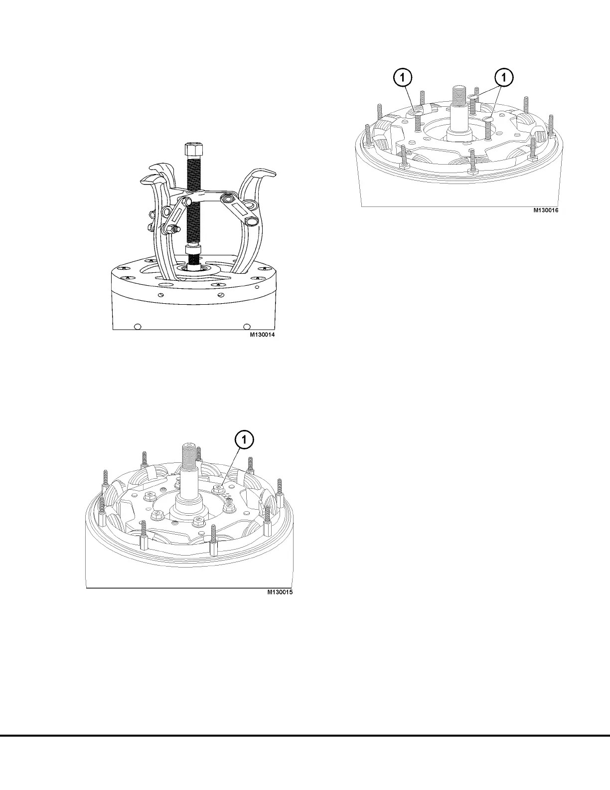
2. With a gear puller, remove end housing from
alternator (Figure 13-10).
REAR ROTOR REMOVAL
1. Remove six flanged locknuts from core studs or
six self tapping screws (1, Figure 13-11). Scribe
location of stud or screw holes on rotor face plate.
2a. Use three 10-32 UNF x 2” long machine screws
as jacks in the three threaded holes of rotor end
plate (Figure 13-12). Pull rotor off of core gradu-
ally by working screws against core in sequence.
If rotor resists movement, see alternate method
below.
Alternate Method
2b. Using an air hammer (air chisel) with a blunt
tipped tool, vibrate the area around the rotor
element to rotor core attaching studs. The vibra-
tions should loosen any built up rust in that area.
Remove the rotor element.
If resistance is still felt, use the method described
in “2a.”, plus the air hammer.
REAR BEARING REMOVAL
There are two types of rear bearing systems in use:
1. For press fit rear bearings, support end housing
on blocks with rear side facing up. Use a proper
tool and press to remove rear bearing and seal.
2. The loose fit rear bearing is retained on the shaft
and core assembly and can be removed with a
pulley puller.
FIGURE 13-10.
FIGURE 13-11.
1. Self-Tapping Screws
FIGURE 13-12.
1. Machine Screws
M13003 04/01 Niehoff Alternator Overhaul Manual M13-13