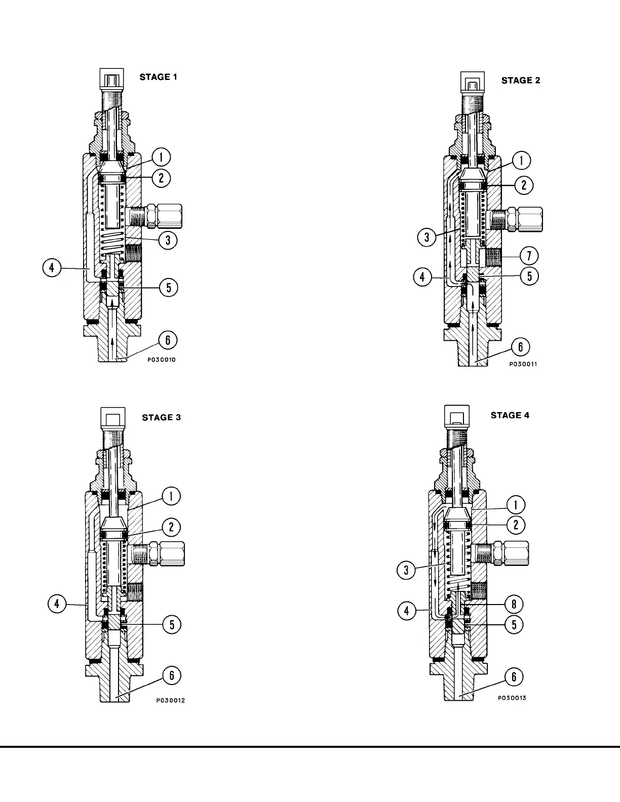
INJECTOR OPERATION
STAGE 1.
The injector piston (2) is in its normal or
“rest” position. The discharge chamber (3)
is filled with lubricant from the previous
cycle. Under the pressure of incoming lubri-
cant (6), the slide valve (5) is about to open
the passage (4) leading to the measuring
chamber (1) above the injector piston (2).
STAGE 2.
When the slide valve (5) uncovers the pas-
sage (4), lubricant (6) is admitted to the
measuring chamber (1) above the injector
piston (2) which forces lubricant from the
discharge chamber (3) through the outlet
port (7) to the bearing.
STAGE 3.
As the injector piston (2) completes its
stroke, it pushes the slide valve (5) past the
passage (4), cutting off further admission of
lubricant (6) to the passage (4) and meas-
uring chamber (1). The injector piston (2)
and slide valve (5) remain in this position
until lubricant pressure in the supply line (6)
is vented.
STAGE 4.
After venting, the injector spring expands,
causing the slide valve (5) to move, so that
the passage (4) and discharge chamber (3)
are connected by a valve port (8). Further
expansion of the spring causes the piston
to move upward, forcing the lubricant in the
measuring chamber (1) through the pas-
sage (4) and valve port (8) to refill the
discharge chamber (3).
Injector is now ready for the next cycle.
P3- 6 Automatic Lubrication System P03018 4/00