Cleaning and Inspection
1. Discard all O-rings and backup rings. Clean all
parts in solvent and dry with compressed air.
2. Inspect all springs for breaks or distortion. Inspect
poppet seating surfaces for nicks or excessive
wear. All seats must be sharp and free of nicks.
3. Inspect all bores and surfaces of sliding parts for
nicks, scores or excessive wear.
4. Inspect poppets in their respective bore for fit.
Poppets should move freely, through a complete
revolution, without binding.
5. Inspect fit and movement between sleeve and
low pressure relief valve.
Assembly
1. Coat all parts including housing bores with clean
type C-4 hydraulic oil. Lubricate O-rings lightly
with a multipurpose grease.
2. If restrictor poppet (2, Figure 8-6) was removed,
reassemble in the order shown.
3. Install check valves (11, Figure 8-5) in their
respective bores. Install springs (12).
4. Install O-rings (10), and cover (13). Install cap-
screws (14). Tighten capscrews to 60 ft. lbs. (81
N.m) torque.
5. Install secondary low pressure relief (7) in sleeve
(6) and install assembly in housing (9). Install
flow control/main relief valve (4). Install springs
(3 & 5). Install cover (2). Install capscrews (1).
Tighten capscrews to 60 ft. lbs. (81 N.m) torque.
Connect external tube, tighten nuts to 25 ft. lbs.
(34 N.m) torque.
REAR SPOOL SECTION
(Work Ports)
Disassembly
NOTE: It is not necessary to remove the inlet sections
(1 or 4, Figure 8-2) to accomplish spool section (2 or
3) disassembly.
1. Match mark or identify each part when removed
in respect to its location or respect to its mating
bore to aid reassembly.
2. Remove capscrews and lift spool section cover
(1, Figure 8-9) from housing.
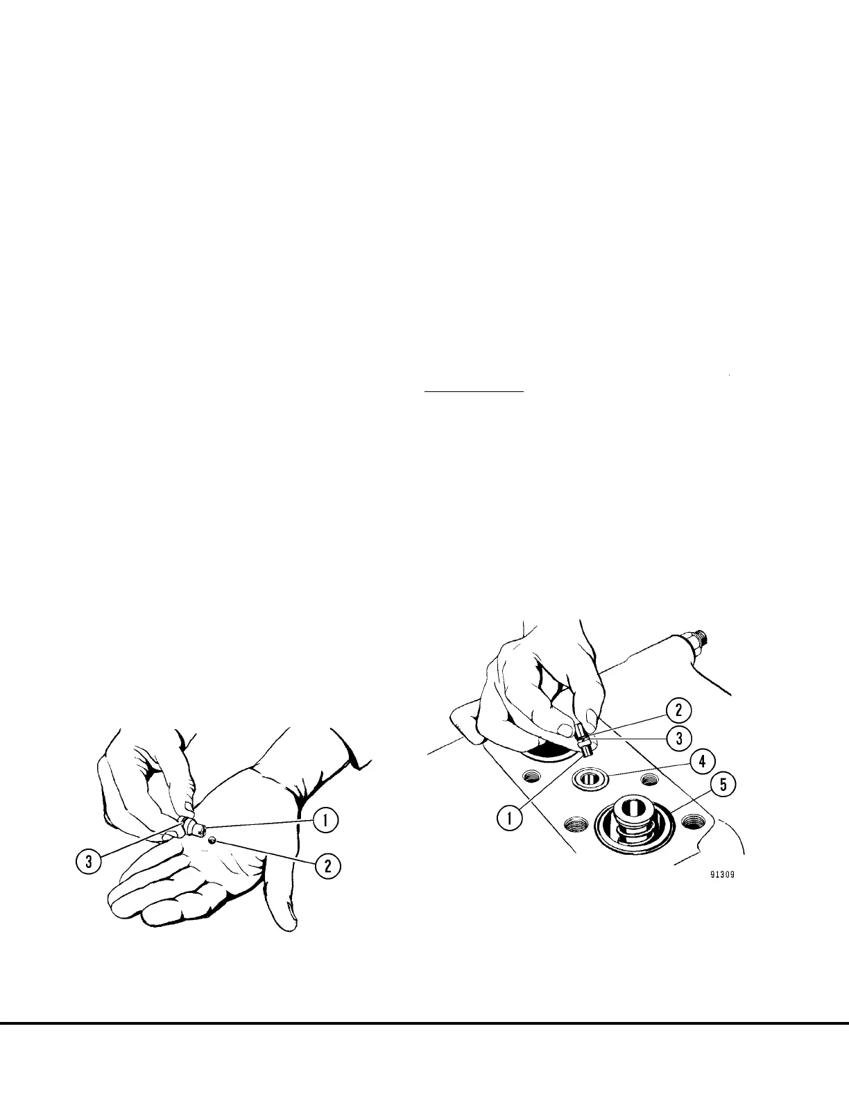
3. Remove poppet (1, Figure 8-7) from spool cover.
Remove and discard O-ring (3).
NOTE: The poppet (1) contains a small steel ball.
Do not misplace.
4. Remove and discard O-rings (4 & 5, Figure 8-8).
5. Remove restrictor poppet (1). Remove and dis-
card O-ring (2) and backup ring (3), if used. Note
the position of the restrictor when removed to
insure correct reassembly.
6. Remove spool assembly (20, Figure 8-9). Note
the color of the lower spring (blue) to insure
proper location during reassembly. Also note the
“V” groove on top end of spool.
FIGURE 8-7. POPPET AND BALL
1. Poppet
2. Steel Ball
3. O-Ring
FIGURE 8-8. RESTRICTOR POPPET REMOVAL
1. Restrictor Poppet
2. O-ring *
3. Backup Ring *
4. O-Ring
5. O-Ring
* NOTE: Items 2 and 3 not used on all valves.
L8-4 Hoist Circuit Component Repair L08024