Assembly of Cylinder
1. Install seals (15, Figure 8-20) and bearing (14)
on second stage cylinder. Install bearings (19)
and buffer seal (18), rod seal (20) and rod wiper
(21) on first stage cylinder. Lubricate with clean
hydraulic oil (Type C-4).
2. Align and slide the second stage cylinder (2)
inside the first stage cylinder (3). Allow the sec-
ond stage to protrude far enough to install the
snap ring (9) on the inside of the first stage
cylinder.
3. Mount the housing (4) in the fixture with the cover
end positioned at the top. Install bearings (19)
and buffer seal (18), rod seal (20) and rod wiper
(21) in the housing.
4. Install lifting tool used during disassembly in the
second and first stage cylinder assembly.
5. Install bearings (13 & 24) on the first stage
cylinder (3). Lift and align this assembly over the
housing (4). Lower the second and first stage
cylinders into the housing.
6. Install retainer used during disassembly to hold
the second and first stage cylinder in place when
the housing is rotated. Rotate housing 180
o
to
position the lower mounting eye at the top.
7. Install bearings (19) and buffer seal (18), rod seal
(20) and rod wiper (21) in the second stage
cylinder (2). Note the proper orientation of the
rod seal (20) backup ring; install with radi-
used corner toward seal and white dot away
from seal.
8. Attach a lifting device to the rod eye (1) and align
it over the housing (4). Lower the rod into the
housing. Lubricate the rod with hydraulic oil.
9. Rotate housing 180° to position the cover end at
the top. Remove retainer installed in Step 5.
Install bearings (17) and seal (16) on the rod
bearing retainer (6).
10. Thread two guide bolts 4 in. (100 mm) long in the
end of the rod (1). Install seal (8) on the end of
the rod.
11. Align piston rod bearing retainer (6) over guide
bolts and lower it over the end of the rod (1).
Remove guide bolts.
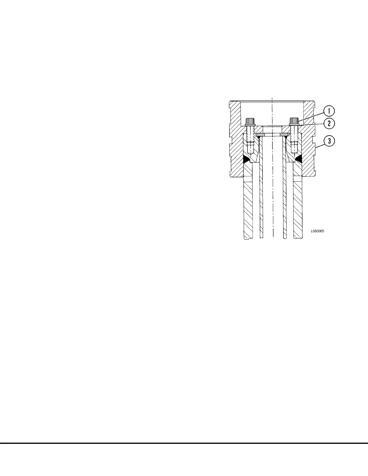
NOTE: Check capscrews (1, Figure 8-24) carefully for
distress and, if in doubt, replace them with new parts.
12. Lubricate capscrews (1, Figure 8-24) with a lith-
ium base grease. Install capscrews and plate (2)
and tighten to 575 ft. lbs. (780 N.m) torque.
13. Install O-ring (12, Figure 8-20) and backup ring
(23) on cover (10). Align and lower cover onto
housing (4). Lubricate capscrews (11), install
capscrews and lockwashers. Tighten capscrews
to 500 ft. lbs. (678 N.m) torque.
14. Install hoist cylinder eye bearing (5, Figure 8-19)
and retainer rings (4) if removed.
FIGURE 8-24. 3rd STAGE PISTON
1. 12 Pt. Capscrew
2. Plate
3. Piston
L08024 Hoist Circuit Component Repair L8-19