Installation
1. Install new O-ring on sensor (4, Figure 20-11) and
install sensor into adapter (3). Tighten sensor to
22–29 ft.lbs. (30–39 N.m) torque
.
2. Install new O-ring on adapter (3) and install com-
plete
adapter/sensor assembly
into valve (2).
Hold valve body and tighten
adapter/sensor
as-
sembly to
103 ft.lbs. (176 N.m) torque
.
3. Connect sensor wiring to truck wiring harness.
The sensors have three wires. Be sure that wires
are connected correctly. (Figure 20-12)
INCLINOMETER
As the truck is tilted fore or aft, the weight distribution
between the front and rear axles changes. To compen-
sate for this, the inclinometer measures the ground
angle at which the truck rests. This data is then sent
to the payload meter so it can calculate the correct
payload weight. The inclinometer is located below the
operator’s center console (passenger seat structure).
Removal
1. Disconnect inclinometer wire lead from harness.
2. Remove the three capscrews, nuts and lockwash-
ers (4, Figure 20-13) and inclinometer (3).
Installation
1. Install inclinometer (3, Figure 20-13) with cap-
screws, nuts and lockwashers (4).
2. Connect inclinometer wiring to the truck wiring
harness. (Figure 20-14)
Be sure that wires are connected correctly.
Adjustment
1. Park the truck on a 0% grade.
2. Loosen the three Inclinometer mounting cap-
screws (4, Figure 20-13) and rotate the Incli-
nometer until a voltage range of 2.6 ±0.1 Volts
can be measured (using aVolt/Ohm Meter) at pins
1 and 2 of the inclinometer electrical harness
connector.
3. Tighten all capscrews (4, Figure 20-13) to stand-
ard torque, after adjustment.
FIGURE 20-12. SENSOR SIDE CONNECTOR VIEW
Pin Number Wire Color Wire Function
1 Black Ground (GND)
2 Red + Power
3 White Signal
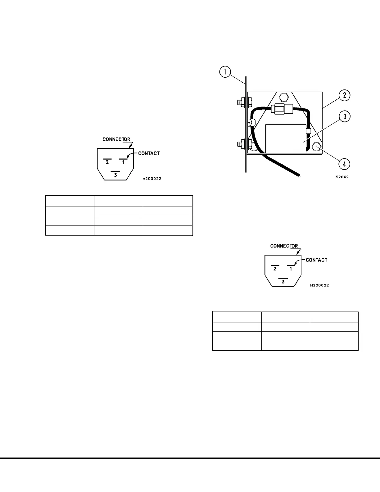
FIGURE 20-13. INCLINOMETER
1. Operator’s Center 3. Inclinometer
Console Frame 4. Capscrew, Nut and
2. Bracket Lockwasher
FIGURE 20-14. INCLINOMETER SIDE
CONNECTOR VIEW
Pin Number Wire Color Wire Function
1 Black Ground (GND)
2 White Signal
3 Red + Power
M20007 10/00 Payload Meter II M20-27