Disassembly
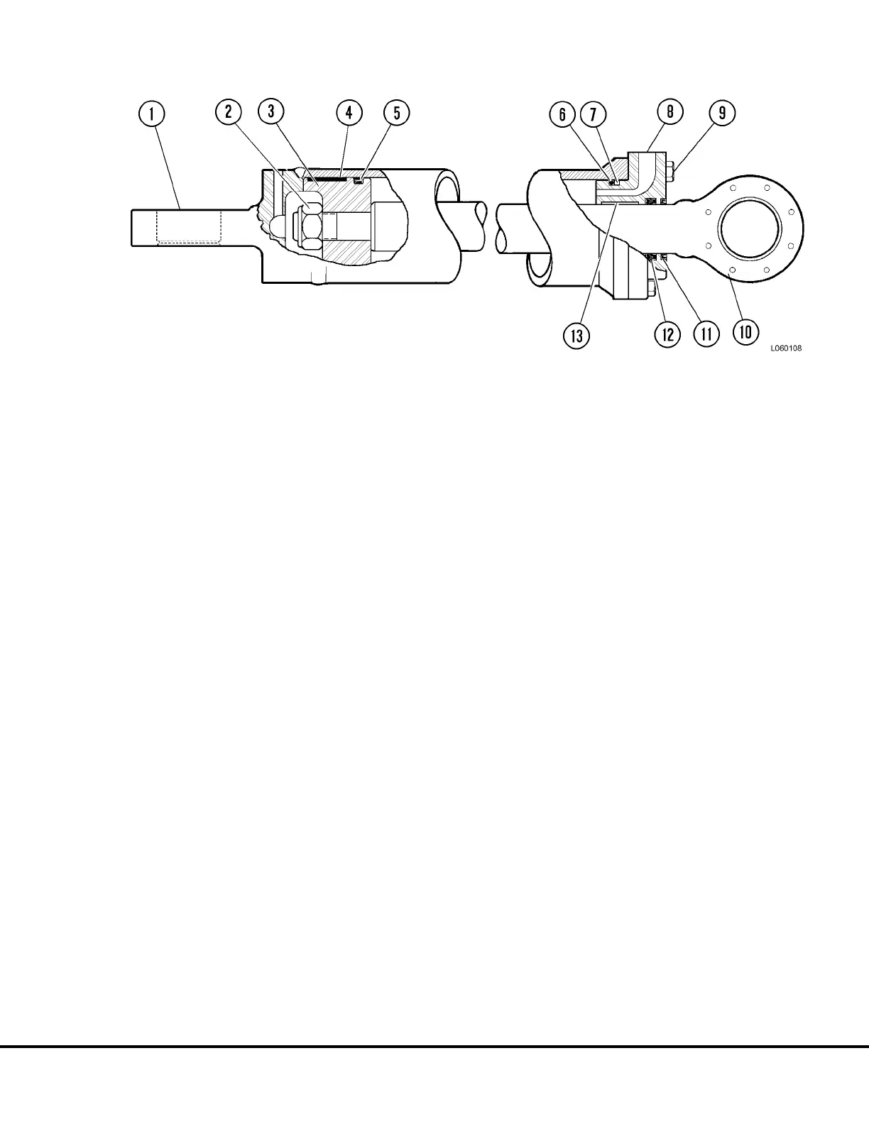
1. Remove capscrews (9, Figure 6-11) and pull rod
(10) and gland (8) out of cylinder housing (1).
2. Remove locknut (2) and piston (3). Remove piston
bearing (4) and piston seal (5) from piston.
3. Pull rod (10) free of gland (8). Remove O-ring (6)
and backup ring (7). Remove rod seal (12) and
rod wiper (11). Remove Bearing (13).
4. Inspect cylinder housing, gland, piston and rod for
signs of pitting, scoring or excessive wear. Clean
all parts with fresh cleaning solvent and lubricate
with clean Type C-4 hydraulic oil.
Piston Seal & Bearing Installation
1. Install new piston seal (5, Figure 6-11) on piston
(3) as follows:
a. Heat piston seal assembly (5) in boiling water
for 3 to 4 minutes.
b. Remove piston seal from water and assemble
on piston. DO NOT take longer than 5 seconds
to complete as seal will take a permanent set.
The piston bearing (4) may be used to position
seal assembly in groove. Apply pressure
evenly to avoid cocking seal.
c. If seal has taken a slightly larger set (loose on
piston) a belt type wrench or similar tool can be
used to compress O.D. of seal until it fits tightly
on piston.
2. Install bearing (4) in piston groove.
Cylinder Assembly
1. Install new bearing (13, Figure 6-11), rod seal (12),
rod wiper (11), backup ring (7) and O-ring (6) in
gland (8).
2. Push rod (10) through top of gland, slowly advanc-
ing rod over rod seal and rod wiper.
3. Install piston assembly (3) on rod. Secure piston
to rod with locknut (2). Tighten locknut to 2000 ft.
lbs. (2712 N.m) torque.
4. Carefully install rod and gland assembly into cyl-
inder (1). Insure backup ring and O-ring are not
damaged during installation of gland.
5. Install capscrews (9). Tighten capscrews evenly
to 310 ft. lbs. (420 N.m) torque.
Test
After cylinder assembly rebuild, perform the following
tests to verify performance is within acceptable limits.
1. Piston leakage must not exceed 1 in
3
/min. (1.6
cm
3
/min.) at 2500 psi (17.5 MPa), port to port.
2. Rod seal leakage must not exceed 1 drop in 8
cycles of operation.
3. Piston break-away force should not exceed 100
psi. (69 kPa).
FIGURE 6-11. STEERING CYLINDER ASSEMBLY
1. Housing
2. Locknut
3. Piston
7. Backup Ring
8. Gland
9. Capscrew
4. Piston Bearing
5. Piston Seal Assembly
6. O-Ring
10. Rod Structure
11. Rod Wiper
12. Rod Seal
13. Bearing
L06021 Steering Circuit Component Repair L6-11