FRONT SUSPENSION
The HYDRAIR
®
II suspensions are hydro-pneumatic
components containing oil and nitrogen gas. The oil
and gas in the four suspensions carry the gross truck
weight less wheels, spindles and rear axle assembly.
The front suspension cylinders consist of two basic
components; a suspension housing attached to the
truck frame and a suspension rod attached to the front
spindle.
Check valves and orifice dampening holes control
suspension travel to provide good ride qualities on haul
roads under loaded and empty conditions.
The front suspension rods also act as kingpins for
steering the truck.
The HYDRAIR
®
II suspension cylinder requires only
normal care when handling as a unit. However, after
being disassembled these parts must be handled care-
fully to prevent damage to the machined surfaces.
Surfaces are machined to extremely close tolerances
and are precisely fitted. All parts must be completely
clean during assembly.
Removal
1. Park unloaded truck on hard level surface. Block
wheels and set parking brake. Remove front
wheel and tire according to “Removal” instruc-
tions in Section “G”, Front Tire and Rim. Remove
front wheel hub and spindle as covered in Section
“G”.
2. Remove boot clamp and boot from around sus-
pension.
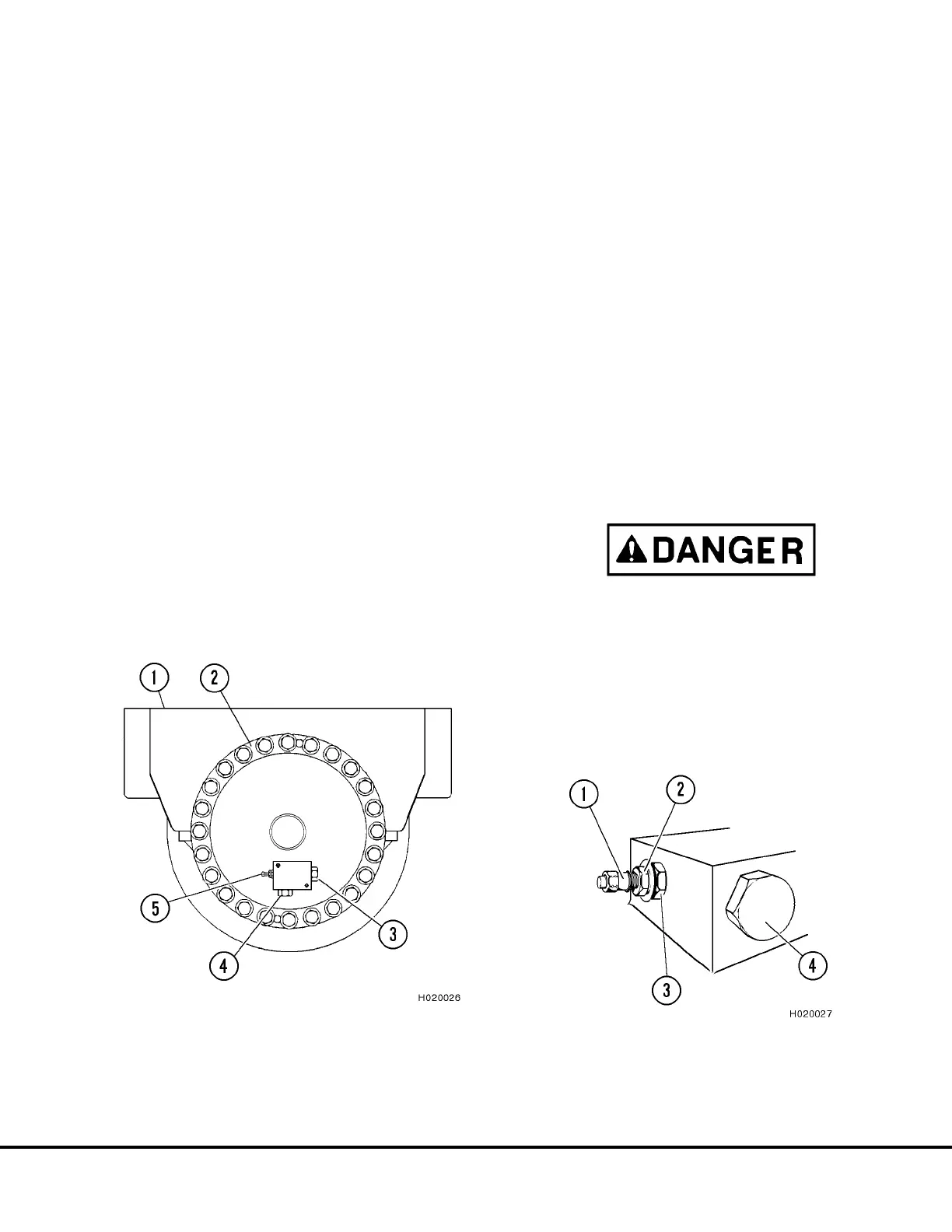
3. Discharge nitrogen pressure from suspension by
removing cap from charging valve (5, Figure 2-1).
Turn the charging valve swivel nut (small hex) (2,
Figure 2-2) counterclockwise 3 full turns to unseat
valve seal (DO NOT turn more than three turns).
DO NOT TURN LARGE HEX (4) (see DANGER
below). Wearing face mask or goggles, depress
valve stem until all nitrogen pressure has been
relieved.
Make certain only the swivel nut (2) turns. Turning
the complete charging valve assembly may result
in the valve assembly being forced out of the
suspension by the gas pressure inside.
4. After all nitrogen pressure has been relieved,
loosen large hex (3) and remove charging valve
assembly. Discard O-ring seal.
FIGURE 2-1. SUSPENSION CHARGING VALVE
1. Suspension
Housing
2. Cap Structure
3. Pressure Sensor Port
4. Vent Plug
5. Charging Valve
FIGURE 2-2. CHARGING VALVE INSTALLATION
1. Valve Cap
2. Swivel Nut (Small Hex)
3. Charging Valve Body (Large Hex)
4. Vent Plug
H02013 2/01 Front Suspensions H2-1