Removal
1. With engine shut down and key switch “Off”, allow
at least 90 seconds for the accumulator to bleed
down. Turn the steering wheel to make sure no
hydraulic pressure is present. Block front and
back of rear wheels.
2. Disconnect hydraulic and lubrication lines at the
steering cylinders. Plug all line connections and
cylinder ports to prevent contamination of hydrau-
lic system.
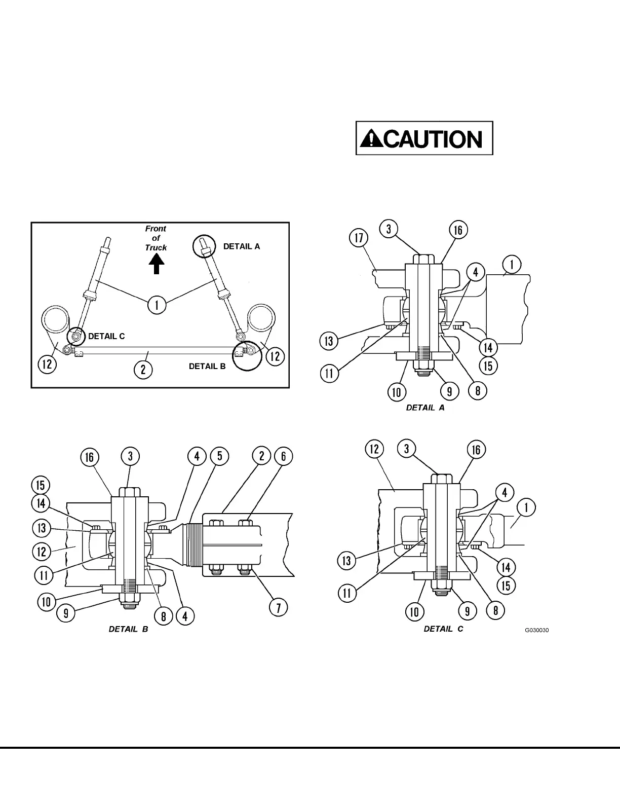
3. Remove locknuts (9, Figure 3-8) capscrews, (3)
and retainers (10) from both ends of assembly.
4. Remove pins (16) from each end of assembly and
move assembly to clean work area.
The bearing spacers and the washers are secured
by the pin. Take measures to prevent components
from falling during removal of pin. Damage to the
components and/or personal injury may result.
FIGURE 3-8. STEERING CYLINDER AND TIE ROD INSTALLATION
1. Steering Cylinder
2. Tie Rod Assembly
3. Capscrew
4. Spacer
5. Tie Rod End
6. Capscrew
7. Locknut
8. Washer
9. Locknut
10. Retainer
11. Bearing
12. Spindle Arm
13. Bearing Retainer
14. Capscrew
15. Washer
16. Pin
17. Frame
G3-10 Front Wheel Hub and Spindle G03017 02/01