FAN ASSEMBLY
1a. Place fan assembly on shaft (Figure 13-39).
Note: If fan hub has ring seals and carrier as ring seal
must compress ring enters housing.
1b. When repairing units manufactured before June
1994, the ring seal and contact seal must be
removed before installing the fan (Refer to Figure
13-34).
2. Use hardened washer and locknut to fasten fan
to alternator. Place alternator and pulley into vise.
With a 3/4” socket, tighten fan nut (Figure 13-39).
Torque fan nut to 50 in. lbs. (68 N.m).
Note: Brass or aluminum jaw protectors must be in-
serted into vise jaws to prevent damage to pullley.
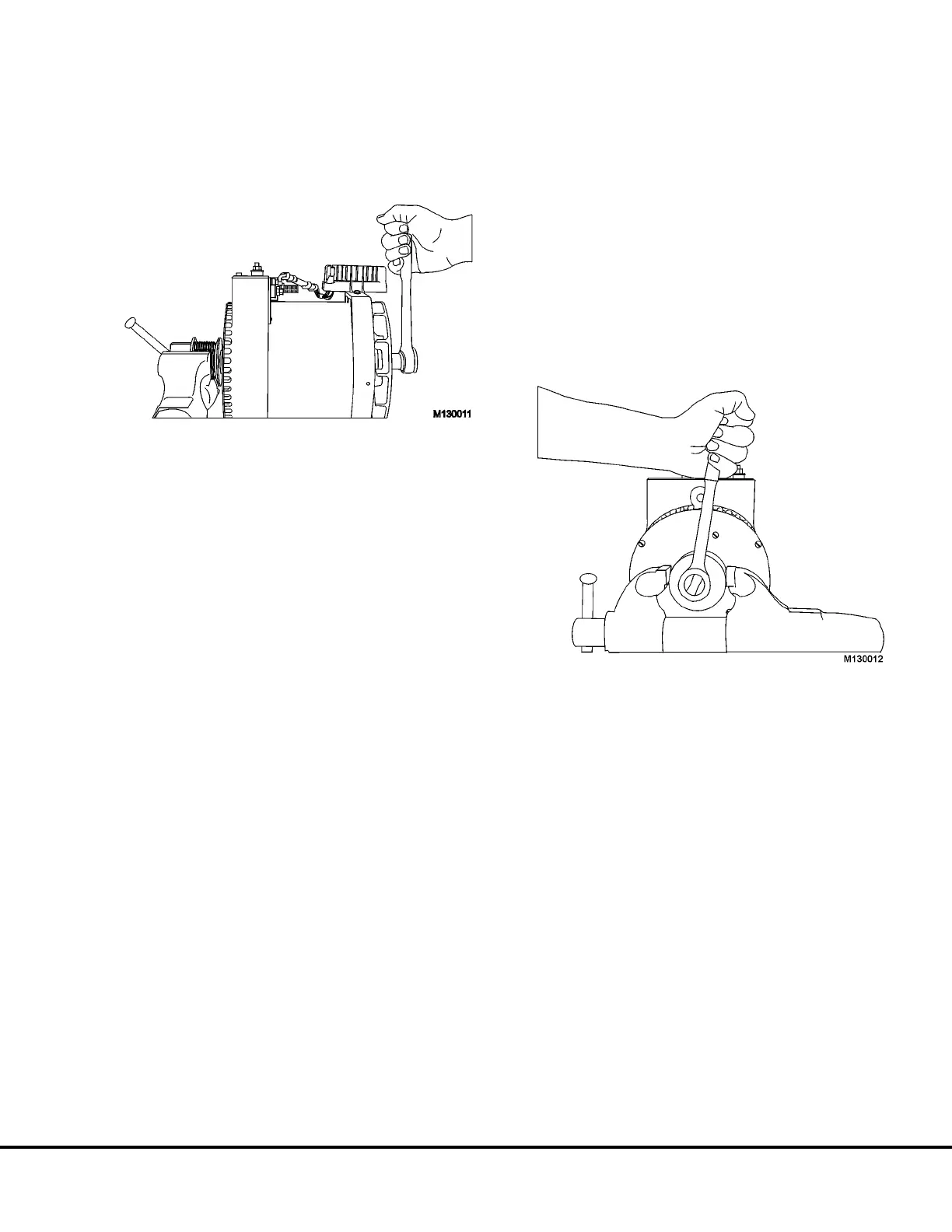
PULLEY ASSEMBLY
NOTE: Do not hold fan to prevent shaft rotation.
Fan damage may result.
1. Install pulley bushing on shaft.
2. Press Woodruff Key into shaft.
3. Position pulley on shaft.
4. Install pulley nut and hardened washer on shaft.
Place alternator and pulley into vise. With a
15/16” socket on the pulley nut (Figure 13-40).
Torque pulley nut to 120 ft. lbs. (162.7 N.m).
Note: Brass or aluminum jaw protectors must be in-
serted into vise jaws to prevent damage to pulley.
FIGURE 13-39.
FIGURE 13-40.
M13003 04/01 Niehoff Alternator Overhaul Manual M13-25