FRONT HOUSING REMOVAL
Note: All control box and front housing connections are
coated with RTV Silicone Rubber. Remove RTV Sili-
cone Rubber as alternator is disassembled.
1. Remove five screws from control box cover.
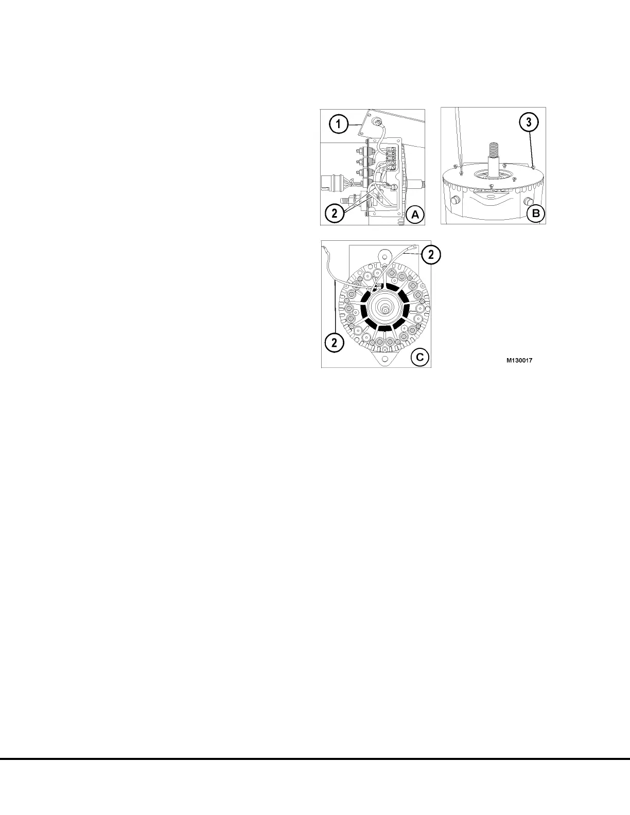
2. Remove control box cover (Figure 13-13 A).
3. Loosen terminal strip screws and disconnect 2
field leads (white wires) from control box terminal
strip.
4. Remove six screws from front housing cover plate
(Figure 13-13 B).
5. Remove front housing cover plate.
6. Remove the six nuts holding phase leads (black
wires) to diode studs (Figure 13-13 C).
7. Remove the six phase leads from the diode studs
and push the phase leads back through the large
openings in front housing (this will facilitate sepa-
ration of front housing from tube).
8. Remove nine flanged locknuts from stator/tube
assembly studs at front of front housing.
Note: The Front housing is attached to the rotor/shaft
core assembly.
9. Separate front housing with the rotor/shaft/core
assembly from the stator/tube assembly. Light
taps with a soft faced mallet will help in the
separation of parts.
10. Support front housing on wood blocks. Using a
press, press shaft through front housing bearing.
FIGURE 13-13.
1. Cover 3. Front Cover Screw
2. Field Leads (white wires)
M13-14 Niehoff Alternator Overhaul Manual M13003 04/01