CONTROL UNIT ASSEMBLY REPLACEMENT
Refer to Figures 13-30 and 13-31 for the following
steps:
1. Hold the new regulator connector harness in its
approximate installation position and bend wires
into their proper position.
2. Solder both the regulator connector lead “3”, and
the output lead from “B+” buss, to the terminal
block, “B+” position. (right of center)
3. Position nuts on the terminal block attaching
screws about 2 threads from the tip of the screw.
NOTE: These nuts are used as spacers.
4. Attach the terminal block to the alternator housing.
CAUTION: Thread both screws in evenly so as not
to cock the terminal block. Failure to keep the
terminal block parallel to the housing may break
the terminal block.
5. Attach the ground lead from the regulator harness
(lead “2”) to the housing.
6. Route the regulator harness under “B+” buss
leads. Care should be taken to keep the regulator
connector flat with “A” pin properly positioned.
NOTE: Wires in steps 7 & 8 should slant away from
both “E” & “R” terminals (down and left, as viewed from
outside).
7. Position the insulating sleeving over wire termi-
nals prior to attaching ring terminals to “E” & “R”
(or phase terminals) studs.
NOTE: Assembly sequence for “E” & “R” terminal (or
phase terminals) is: insulator-flat washer-terminal-nut.
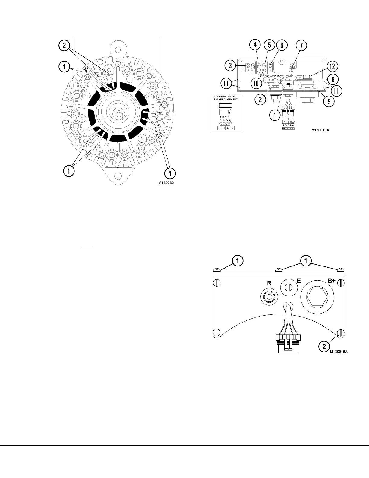
FIGURE 13-29.
1. Field Leads 2. Phase Leads
FIGURE 13-30. CONTROL UNIT ASSEMBLY
1. Ignition (E) (Harness Lead #4)
2. Relay (R)
3. Terminal Block
4. F- (Harness Lead #1)
5. F+ (Harness Lead #3); 10 in. lbs. (1.3 Nm) torque
6. Terminal Block Screw; 30 in. lbs. (3.5 Nm) torque
7. Ground Wire from Regulator (Harness Lead #2)
24 in. lbs. (2.7 Nm) torque
8. B+ Buss Leads to Rectifier
9. When replacing output stud only; tighten to
12-15 ft.lbs. (16-20 N.m) torque, and coat with
epoxy.
10. Solder here.
11. Apply RTV here.
12. Tighten to 180 in.lbs. (20 N.m) torque.
FIGURE 13-31.
1. Cover Screws (TOP) 2. Control Unit Screw
Tighten nine screws to 20 in.lbs. (2.3 N.m) torque.
M13003 04/01 Niehoff Alternator Overhaul Manual M13-21