RETARDER CONTROL LEVER (STEERING COLUMN-MOUNTED)
Due to wear, the Retarder Control Lever assembly (4,
Figure 3-30) may occaionally require adjustment or
repair.
Lever Assembly Removal
Adjustment of the lever assembly or replacement of
the potentiometer requires removal of the assmbly
from the steering column.
1. In the operator cab, remove the capscrews (1,
Figure 3-30) and lockwashers (2) from steering
column (3).
2. Disconnect harness connecter (5) from lever as-
sembly (4).
Lever Assembly Installation
1. Connect harness connecter (5, Figure 3-30) to
lever assembly (4).
Install lever assembly to steering column (3).
2. Install capscrews (1) and lockwashers (2).
Tighten socket head capscrews to 36 in. lbs. (4.1
N.m) torque.
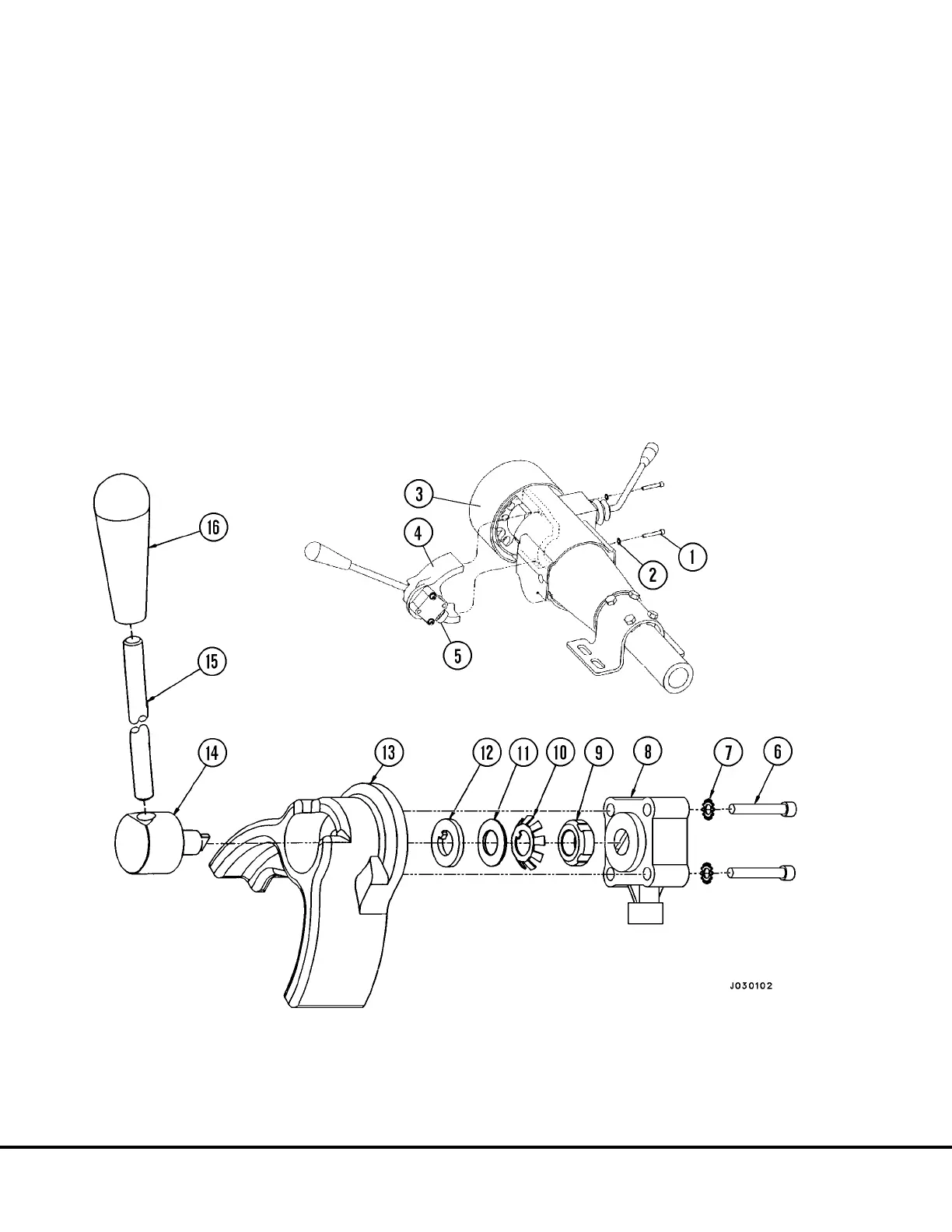
FIGURE 3-30. COLUMN-MOUNTED RETARDER CONTROL LEVER
1. Capscrew, Socket Hd. 5. Harness Connector 9. Locknut 13. Bracket
2. Lockwasher 6. Capscrew, Socket Hd. 10. Washer, Tanged 14. Shaft
3. Steering Column Assy. 7. Lockwasher 11. Spring, Disc 15. Lever
4. Retarder Control Assy. 8. Potentiometer (Switch Assy.) 12. Washer, Internal Tang 16. Handle
J3-30 Brake Circuit Component Service J03019 1/99