INLET SECTION
Disassembly
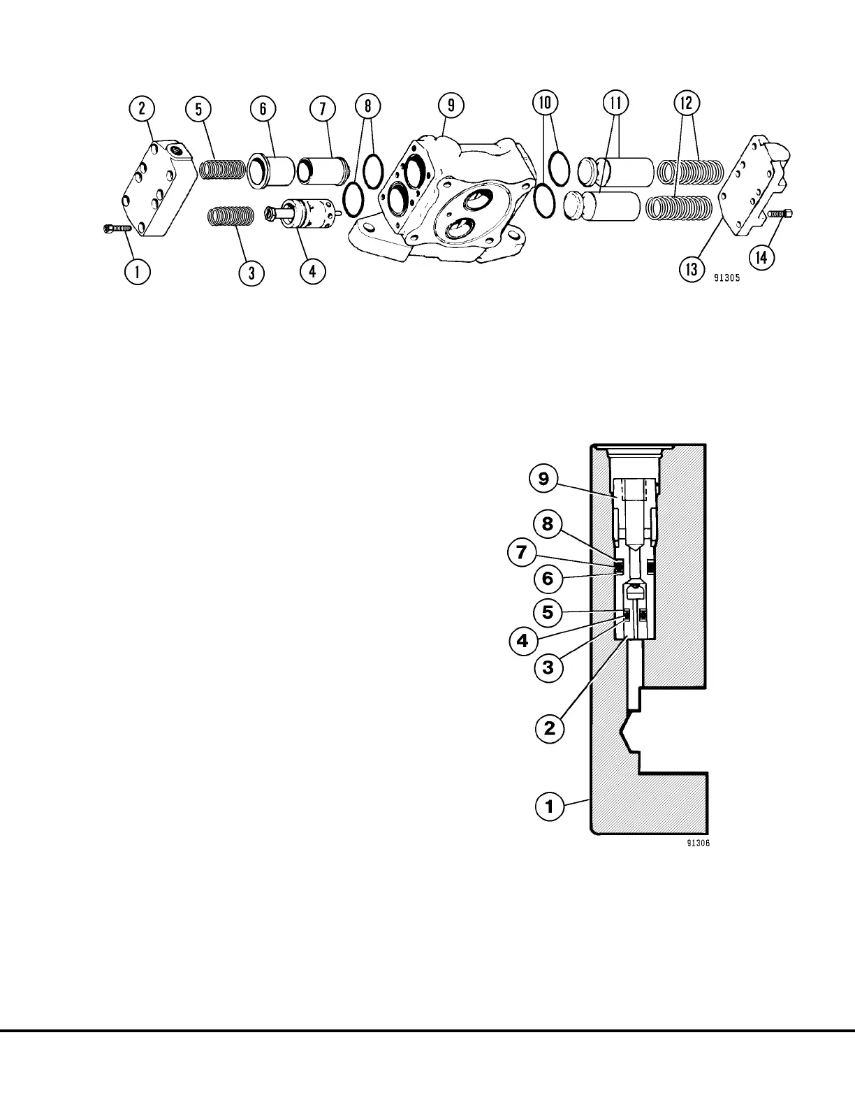
1. Match mark or identify each part when removed
in respect to its location or respect to its mating
bore to aid reassembly.
2. Disconnect the external tube (7, Figure 8-2) at
the cover end and remove. Remove capscrews
(14, Figure 8-5), remove cover (13). Remove
springs (12), check valves (11) and O-rings (10).
NOTE: Inlet section shown removed from main valve
body for clarity.
3. Remove capscrews (1) and cover (2). Remove
springs (3 & 5) and flow control/main relief valve
(4). Remove sleeve (6), low pressure relief (7)
and O-rings (8).
NOTE: If restrictor poppet removal in cover (2, Figure
8-5) is required, refer to step 4 and figure 8-6.
4. Remove sleeve (9), backup ring (8), O-ring (7),
backup ring (6). Remove backup ring (5), O-ring
(4), backup ring (3) and restrictor poppet (2).
5. Repeat steps 1 through 4 for the opposite inlet
section if disassembly is required.
FIGURE 8-6. RESTRICTOR POPPET REMOVAL
(Inlet Cover)
1. Inlet Cover
2. Restrictor Poppet
3. Backup Ring
4. O-Ring
5. Backup Ring
6. Backup Ring
7. O-ring
8. Backup Ring
9. Sleeve
FIGURE 8-5. INLET SECTION DISASSEMBLY
1. Capscrew
2. Inlet Cover
3. Spring (Orange)
4. Flow Control & Main Relief Valve
5. Spring
6. Sleeve
7. Secondary Low Pressure Relief
8. O-Rings
9. Inlet Valve Body
10. O-Rings
11. Check Valves
12. Springs
13. Cover
14. Capscrews
L08024 Hoist Circuit Component Repair L8-3