OILING AND CHARGING PROCEDURE
GENERAL
These procedures cove the Oiling and Charging of
HYDRAIR
®
II suspensions on Komatsu Trucks.
Suspensions which have been properly charged will
provide improved handling and ride characteristics
while also extending the fatigue life of the truck frame
and improving tire wear.
NOTE: Inflation pressures and exposed piston lengths
are calculated for a normal truck gross vehicle weight
(GVW). Additions to truck weight by adding body lin-
ers, tailgates, water tanks, etc. should be considered
part of the payload. Keeping the truck GVW within the
specification shown on the Grade/Speed chart in the
operator cab will extend the service life of the truck
main frame and allow the HYDRAIR
®
II suspensions to
produce a comfortable ride.
All HYDRAIR
®
II suspensions are charged with
compressed nitrogen gas with sufficient pressure
to cause injury or damage if improperly handled.
Follow all safety instructions, cautions, and warn-
ings provided in the following procedures to pre-
vent any accidents during Oiling and Charging.
Proper charging of HYDRAIR
®
II suspensions requires
that three (3) basic conditions be established in the
following order:
1. Oil level must be correct.
2. Suspension piston rod extension for nitrogen
charging must be correct and this dimension be
maintained during nitrogen charging.
3. Nitrogen charge pressure must be correct.
For best results, HYDRAIR
®
II suspensions should be
charged in pairs (fronts together and rears together).
If rears are to be charged, the fronts should be charged
first.
NOTE: Set up dimensions specified in the charts must
be maintained during oiling and charging procedures.
However, after the truck has been operated, these
dimensions may vary.
EQUIPMENT LIST
HYDRAIR
®
Charging Kit
Jacks and/or Overhead Crane
Support Blocks (Front and Rear) for:
• Oiling Height Dimensions
• Nitrogen Charging Height Dimensions
HYDRAIR
®
Oil (See Specifications Chart)
Dry Nitrogen (See Specifications Chart)
HYDRAIR
®
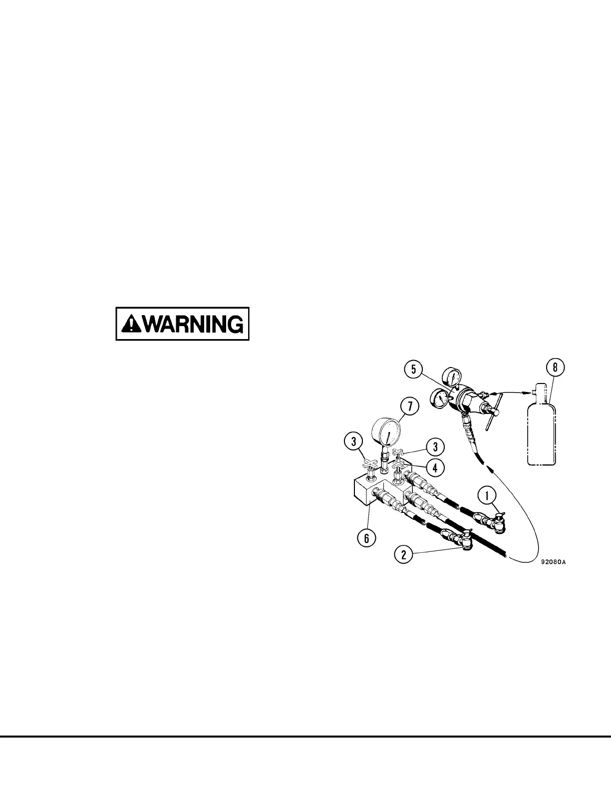
CHARGING KIT
Assemble service kit as shown in Figure 4-1 and attach
to container of pure dry nitrogen (8).
Installation of Charging Kit
1. Remove protective covers and charging valve
caps from suspensions to be charged.
2. Turn “T” handles (1, Figure 4-1) of adapters (2)
completely counterclockwise.
FIGURE 4-1. HYDRAIR
®
CHARGING KIT
NOTE: Arrangement of parts may vary from illustration
above, depending on Charging Kit P/N.
1. “T” Handle Valve
2. Charging Valve Adapter
3. Manifold Outlet Valves (from gauge)
4. Inlet Valve (from regulator)
5. Regulator Valve (Nitrogen Pressure)
6. Manifold
7. Charging Pressure Gauge (Suspensions)
8. Dry Nitrogen Gas (Specifications Figure 4-5)
H04005 9/99 Oiling and Charging Procedures H4-1
730E, 830E, and 930E