45. Depress the brake pedal very slowly until the brake
differential pressure switch activates the low brake
pressure lamp and buzzer.
Verify fault indicators are activated at:
Refer to Table I Pressures.
* Record Pressure on data sheet.
Table I - Differential Pressure Switch
Adjustment
Spring
Color
Pressure - Switch Contacts Closing
“B1” Valve Spool “B2” Valve Spool
Red
300 ±30 psi
(2 068 ±207 kPa)
300 ±30 psi
(2 068 ±207 kPa)
Green
600 ±50 psi
(4 137 ±345 kPa)
600 ±50 psi
(4 137 ±345 kPa)
! WARNING ! DO NOT attempt to adjust a "red"
spring to 600
±
50 psi (4 137
±
345 kPa). This will
cause the spring to "bottom out" and the warning
switch will not function properly.
For more specific details regarding Table I, refer
to previous chapter:
BRAKE CIRCUIT COMPONENT SERVICE,
BRAKE VALVE,
"Differential Pressure Switch Adjustment".
46. Shut down the engine and turn key switch OFF.
Allow steering accumulators to bleed down.
47. Open both accumulator bleeddown valves and
bleed entire brake system. Close valves after all
pressure is released.
48. Reconnect hose (4, Figure 4-4) to Tee at “AF1”
port, bottom of hydraulic cabinet
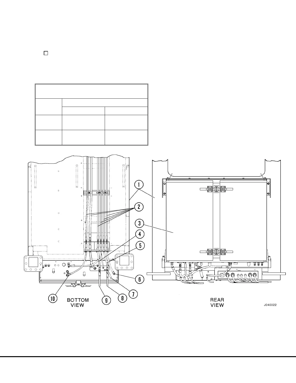
FIGURE 4-4. HYDRAULIC COMPONENTS CABINET
1. Operator’s Cab
2. Hoses to Brake Valve & Steering
Control Valve
3. Hydraulic Components Cabinet
4. To Brake Valve, Port “P2”
5. To Brake Valve, Port “P1”
6. To Brake Valve, Port “B1”
7. To Rear, Frame Mounted Brake
Accumulator
8. To Rear Axle Junction Block, Port “P1”
9. To Front, Frame Mounted
Brake Accumulator
10. To Brake Valve, Port “B2”
J04025 Brake Circuit Checkout J4-7