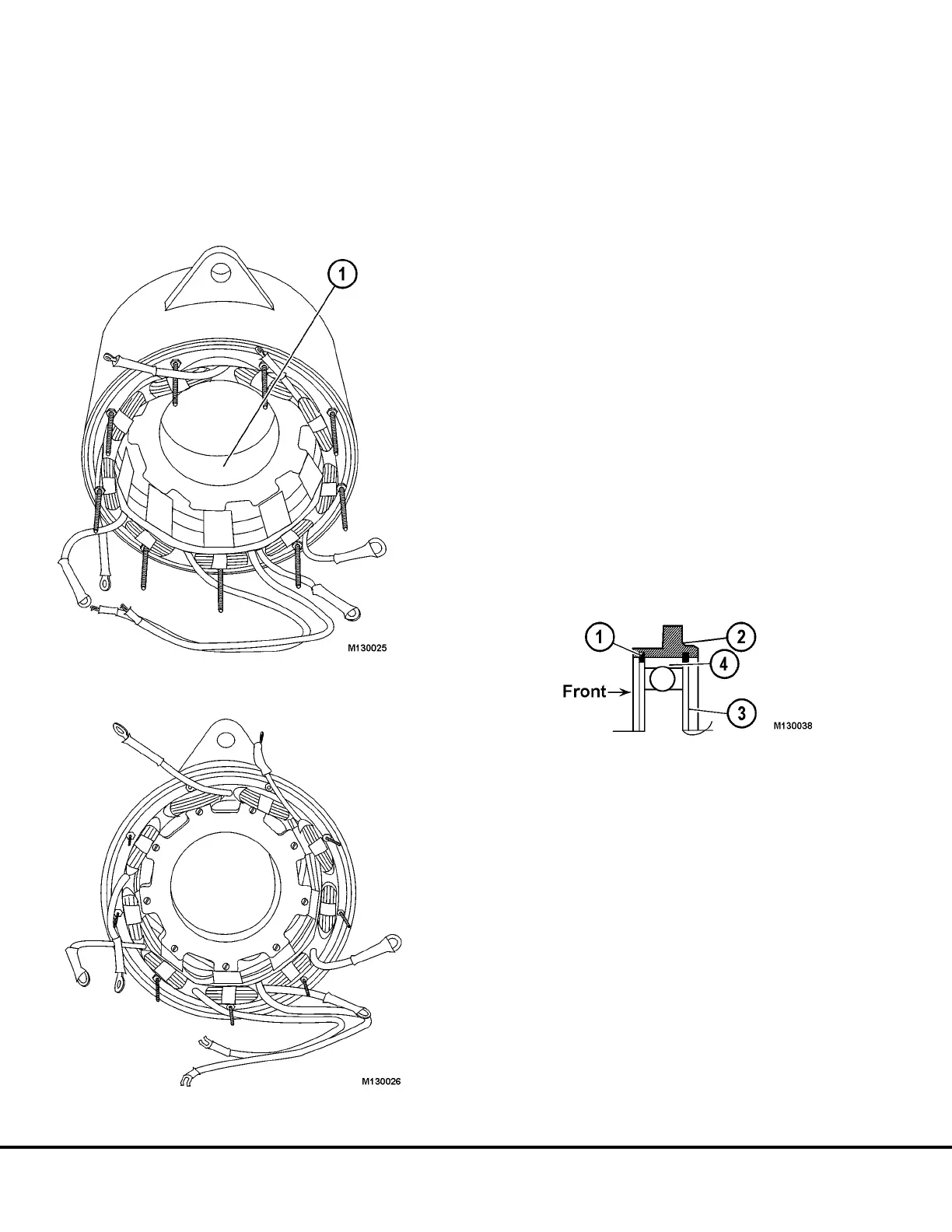
4. Seat field coil bobbin ears over stator tabs (Figure
13-21) by inserting field winding and rotating
about 20 degrees after insertion with tool BF4820.
Align screw holes in bobbin ears with screw holes
in stator tabs.
Note: Bobbin ears go over stator tabs as viewed from
both ends of tube assembly.
5. Make sure field coil leads (white spade terminals)
are pulled through proper stator openings with no
slack at the field coil and that neither wire is
pinched by the bobbin ears.
6. Using eighteen screws coated with loctite, fasten
field coil bobbin ears to stator tabs (Figure 13-22).
Tighten screws to 8-10 lb-in. (0.9- 1.1 Nm) torque.
Note: If field coil leads cannot be threaded through
stator openings with the terminal attached, unsolder
terminals, remove sleeving and then insert leads. After
field coil is in place slip sleeving on field leads, resolder
terminals to wires and slip sleeving back over terminal.
FRONT BEARING ASSEMBLY
1. Clean bearing I.D. surface of front housing.
2. Install retaining ring in rear inner groove of front
housing.
Note:
This retaining ring has two flat sides (3, Figure 13-23).
3. Coat outer race of front bearing (4, Figure 13-23)
with thin coat of loctite.
FIGURE 13-21.
1. Field Coil Bobbin Ear
FIGURE 13-22.
FIGURE 13-23.
1. Retaining Ring (Tapered)
2. Front Housing
3. Retaining Ring (Flat, both sides)
4. Bearing - Outer Race
M13-18 Niehoff Alternator Overhaul Manual M13003 04/01