23. After the brake assembly is properly positioned on
the adaptor, remove the alignment studs and in-
stall the remaining brake adaptor/brake assembly
mounting capscrews (20) and hardened flatwash-
ers (21). Tighten capscrews to 1995 ft. lbs. (2705
N.m) torque.
24. Install bearing retainer pin (40) in groove in spin-
dle. Align and slide outer bearing cone (7) over
pin. Lubricate the bearing with clean hydraulic oil.
25. Install the shim pack, retainer, capscrews, and
hardened washers. Tighten capscrews alternately
to 750 ±
±±
±75 ft. lbs. (1017 ±
±±
±100 N.m) torque in
several successive increments while rotating the
hub.
26. Install a new O-ring (41) on cover (5). Install the
cover, capscrews, and washers. Tighten the cap-
screws to standard torque.
27. Remove socket head capscrews (34) securing
seal retainer (37) to brake assembly (18).
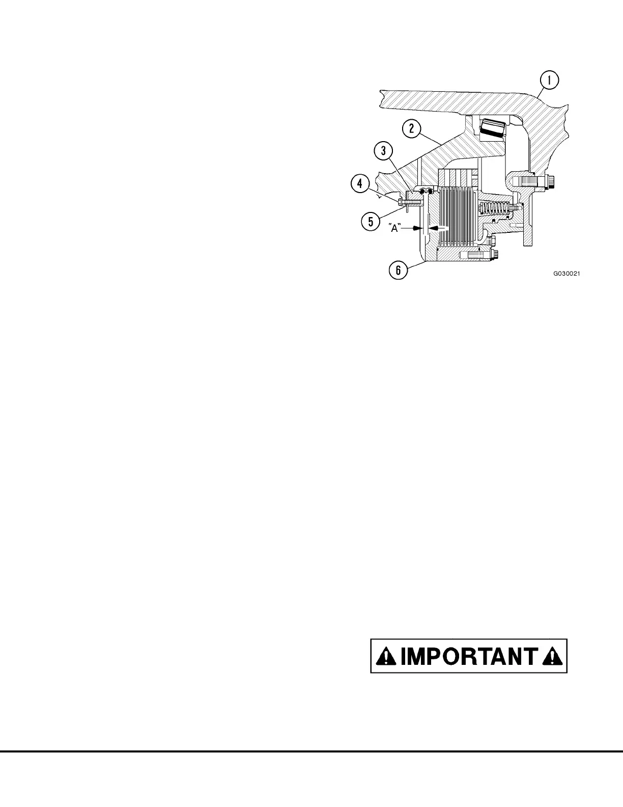
Seal Assembly Gap Check:
After the assembly of the wheel and brake is complete,
the gap between seal carrier (3, Figure 3-7) and the
brake assembly back plate (6) must be measured and
adjusted if necessary.
The ideal gap is 0.433 in (11.0 mm). If necessary, the
gap must be adjusted, using shims as required to
maintain a minimum gap of 0.423 in (10.75 mm) to
0.443 in (11.25 mm) maximum.
28. Measure seal gap as follows:
a. Measure gap, dimension “A”, Figure 3-7 at
three, equally spaced places and record the
result.
b. Add the three dimensions and divide the result
by 3 to obtain the average gap width
29. If average gap width is not between the minimum
and maximum allowable range, loosen the seal
retainer capscrews (4, Figure 3-6) and add shims
(5) as required to reduce the gap or remove shims
to increase the gap.
The quantity and thickness of shims at each of
the six locations must be equal
.
30. Re-tighten seal retainer capscrews to standard
torque and measure gap as described in step 26.
If necessary, repeat step 27 until the proper gap
is maintained.
31. Install speed sensor(s) (16, Figure 3-6) in support
bracket(s) (17). Adjust sensor gap as follows:
a. Rotate hub to position the top of a gear tooth
directly under the sensor tip.
b. Insert a 0.060 in (1.5 mm) feeler gauge be-
tween sensor tip and gear tooth and adjust
sensor clearance.
c. Tighten capscrew to lock sensor in place.
d. Rotate hub 180° and verify clearance remains
within 0.040 in (1.0 mm) minimum to 0.080 in
(2.0 mm) maximum.
32. Install speed sensor cables.
33. Install hub and spindle assembly on suspension
per instructions in "Installation".
STEERING CYLINDERS AND TIE ROD
The steering cylinders and tie rod mounting arrange-
ments are similar. The removal and installation instruc-
tions are applicable to both.
Always install pin retaining capscrews from the
top with the locknut on the bottom side at spindle
arm as shown in Figure 3-8.
FIGURE 3-7. MEASURING SEAL GAP
1. Spindle
2. Wheel Hub
3. Seal Carrier
4. Capscrews
5. Shims
6. Brake Back Plate
G03017 02/01 Front Wheel Hub and Spindle G3-9