To replace a circuit panel card
DO NOT remove the small screws that hold the cover
plate to the circuit panel. Replace circuit panel as a
complete assembly.
1. Place battery disconnect switches in the “OFF”
position.
2. Remove the two mounting screws (6, Figure 3-6)
and carefully remove the circuit panel card from
the relay board.
3. Line up the new circuit panel in slots and with the
socket on the relay board and install carefully.
4. Install two mounting screws (6).
RELAY BOARD IDENTIFICATION
The six relay boards are identified as follows:
(Refer to Figure 3-3 for location.)
• Relay Board 1. . . . . . . . . . Clearance/Turn Signal
• Relay Board 2. . . . . . . . . . . . . . . . . Payload Meter
• Relay Board 3. . . . . Stop, Retard, Backup Lights
• Relay Board 4. . . . . . . . . . . Parking Brake, Horn,
. . . . . . . . . . . . . . . . . . Body-up, Engine Cranking
• Relay Board 5. . . . . . . . . . . . . . . . . . Head Lights
• Relay Board 6. . . . . . . . . . . . . Engine Functions,
. . . . . . . . . . . . . . . . Mid/Full Load Signals to PSC
. . . . . . . . . . . . . . . . . . . . . . Backup Lights & Horn
Refer to Circuit Breaker Chart for electrical circuit iden-
tification numbers.
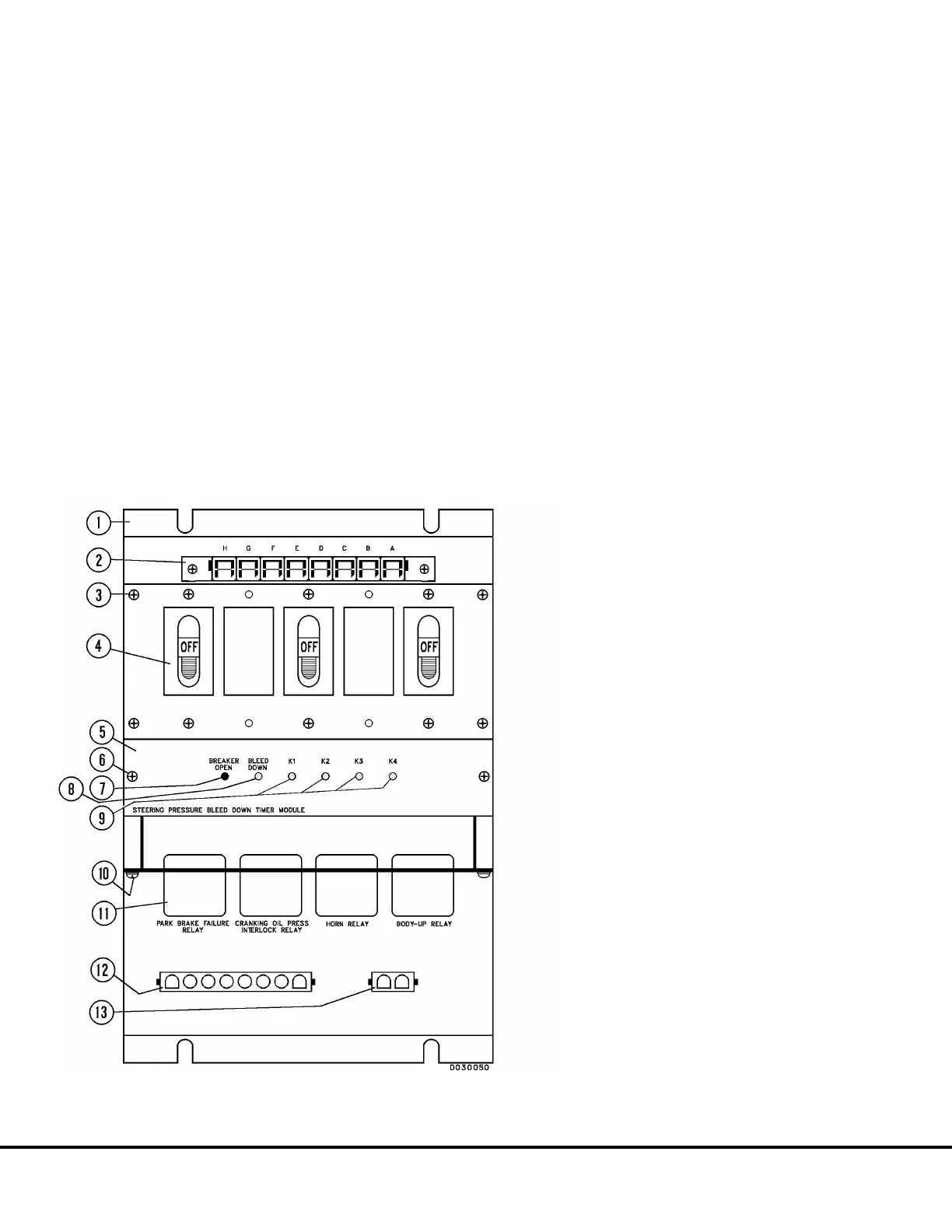
FIGURE 3-6. TYPICAL RELAY BOARD
(RB4 Shown)
1. Relay Board
2. Main Harness Connector
3. Screw
4. Circuit Breaker
5. Circuit Panel Card
6. Screw
7. Breaker Open Light (RED)
8. Bleed Down Light (GREEN)
(Relay Board 4 Only)
9. K1, K2, K3, K4 Lights (GREEN)
10. Screw
11. Relay
12. Circuit Harness Connector
13. Circuit Harness Connector
D3-10 24VDC System Components D03019 04/01