9. Select three capscrews 120° apart and mark
them.
a. Tighten the marked capscrews to 30 ft. lbs. (41
N.m) torque. (Snug the remaining capscrews
after each of the marked capscrews are tor-
qued in the following steps.)
b. Re-tighten the marked capscrews until the gap
between the cap structure and piston housing
is equalized.
c. Re-tighten the marked capscrews in 20 ft. lbs.
(27 N.m) increments until fully tight - 90 ft. lbs.
(122 N.m) torque.
d. Tighten the remaining capscrews to 90 ft. lbs.
(122 N.m) torque.
Pressure Test:
10. Install the O-ring plug and bleeder (17). Install a
fitting in one of the pressure supply ports and
attach a hydraulic power source. Install an O-ring
plug in the remaining port.
a. Slowly apply pressure and open the bleeder
valve to bleed air from the piston cavity. Close
the bleeder and apply 300 psi (2068 kPa) hy-
draulic pressure and hold for one (1) minute.
b. Observe for oil leakage. NO leakage is permit-
ted.
c. If leakage occurs, the brake assembly must be
disassembled and repaired.
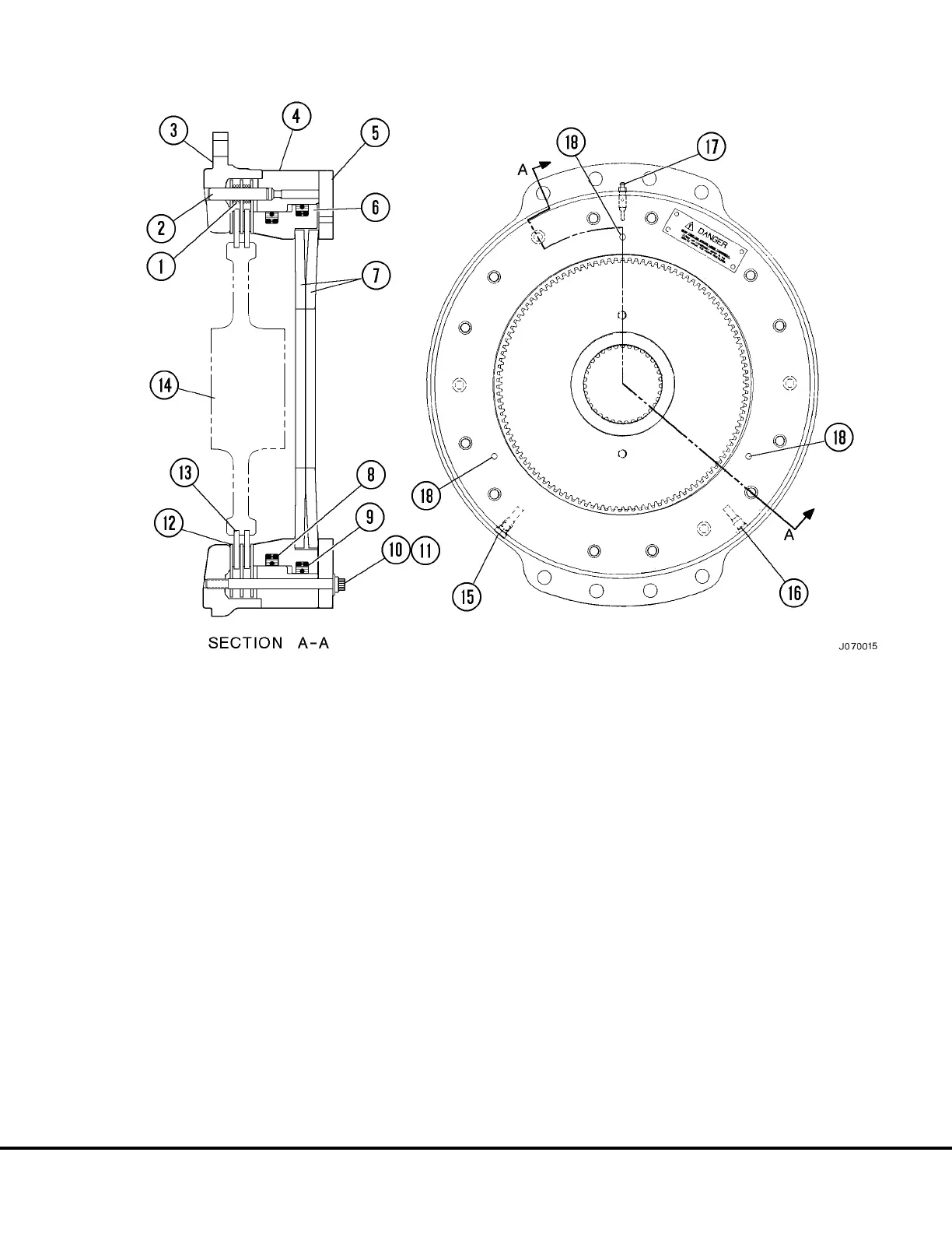
FIGURE 7-2. PARKING BRAKE ASSEMBLY
1. Compression Spring
2. Dowel Pin
3. Housing
4. Piston Housing
5. Endcap Structure
6. Piston
7. Belleville Springs
8. Piston Seal Assembly
9. Piston Seal Assembly
10. Capscrew
11. Hardened Washer
12. Separator Disc
13. Friction Disc
14. Gear (Armature)
15. Plug
16. Oil Supply Port
17. Bleeder & O-Ring Plug
18. Piston Position Holes
J07010 12/98 Parking Brake J7-5