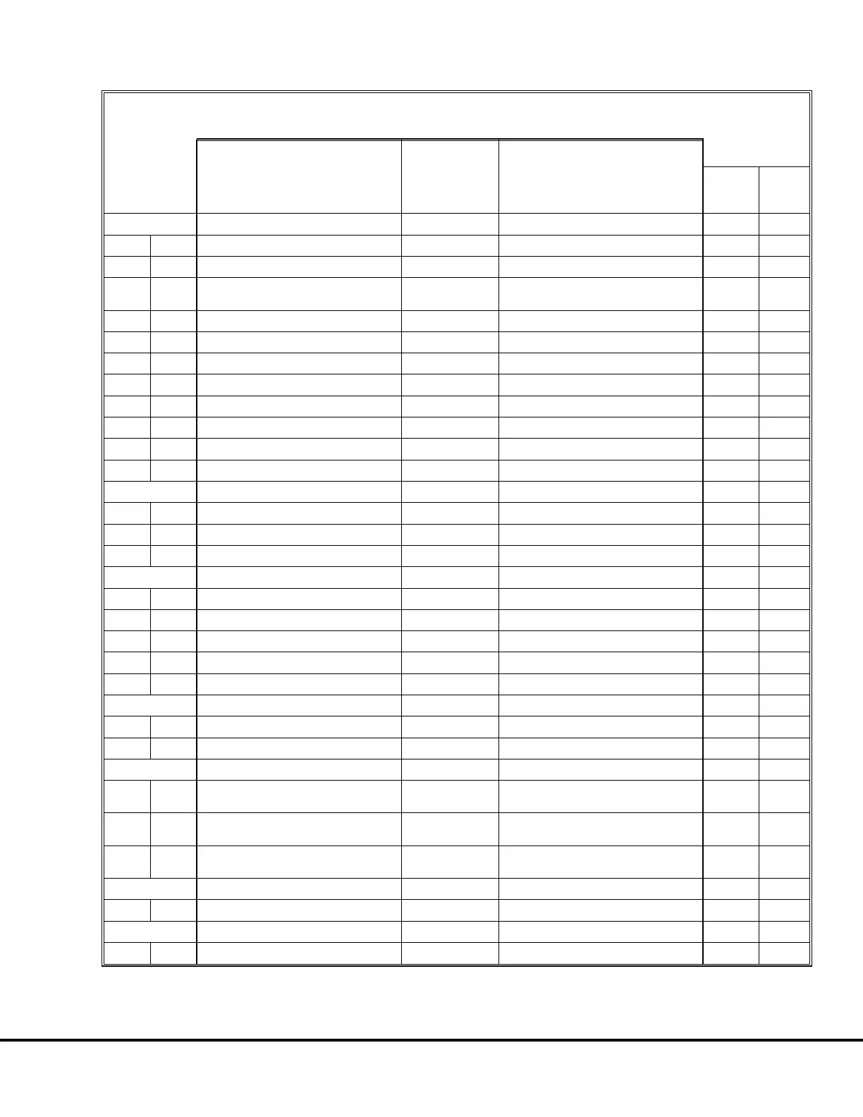
TABLE III: DID PANEL FAULT CODES
(Codes Received From Inverter 1, 2)
EVENT
DESCRIPTION
EVENT
RESTRICTION
DETECTION
INFORMATION
EVENT
NUMBER
Limp
Possible
Lockout
Limit
103/203 (cont.)
:21 link V too hi No power Link voltage too positive
:22 infilV too hi No power Input filter voltage too positive
:23 DB chop VCO hi No power
High freq. on VCO DB chopper
channel
:24 DB chopV too hi No power DB chopper voltage too positive
:25 VA VCO hi No power High freq. on VCO VA channel
:26 VB VCO hi No power High freq. on VCO VB channel
:27 VC VCO hi No power High freq. on VCO VC channel
:28 VA volts too hi No power VA voltage too positive
:29 VB volts too hi No power VB voltage too positive
:30 volt scale C flt No power Scale C volts out of range 70%, 120%
:31 VC volts too hi No power VC voltage too positive
104/204 FIBER OPTIC CARD
:01 fo ps low No power Fiber optic power supply monitor
:02 fo card disable No power Fiber optic card disabled
:03 fo card enable No power Fiber optic card enabled and no dir
105/205 POWER SUPPLY CARD
:01 P5V not ok No power +5 volt not in tolerance
:02 P15V not ok No power +15 volt not in tolerance
:03 N15V not ok No power -15 volt not in tolerance
:06 P24V not ok No power +24 volt not in tolerance
:07 N24V not ok No power -24 volt not in tolerance
106/206 DC WIRING
:01 DC pwr conn open No power DC power connection open
:02 link V phase V mismatch No power Link and phase voltage mismatch
107/207 GDPS FAILURE
:01 gate dr ps off No power
No power to gate drive power supply
or it failed
:02 gate dr ps off S No power
No power to gate drive power supply
or it failed with enable/DC volts
:03 multiple GTO not off S No power
Multiple GTOs not off with enable/DC
volts
109/209 LINK VOLTS SENSOR
:01 linkV sensor flt No power Link voltage sensor failed
111/211 INPUT VOLTS SENSOR
:01 Vfil not ok No power Filter voltage outside limits
E02014 3/01 Electrical Propulsion System Components E2-15
 Loading...


