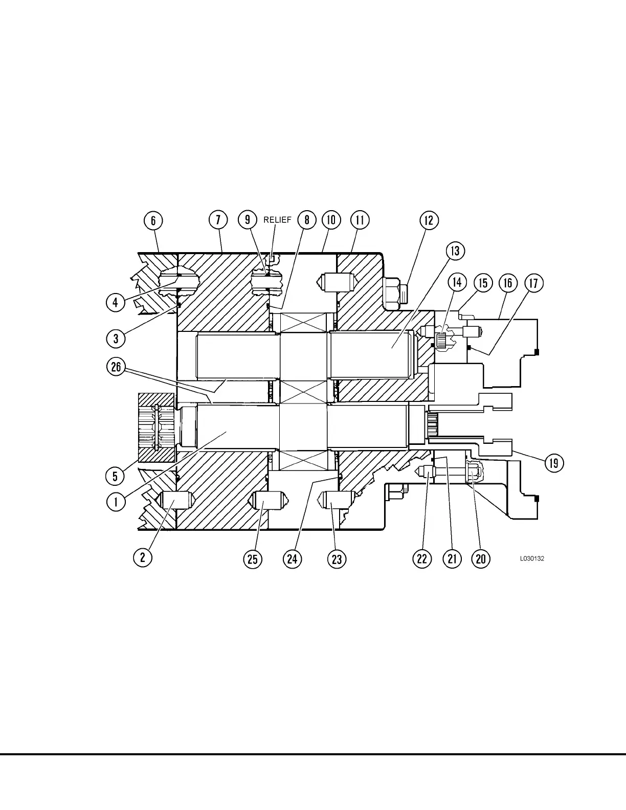
18. Lubricate O-ring (3, Figure 3-15) and install in
bearing plate (7). Lubricate O-rings (4) and install
over studs (12). Replace dowel (2) if removed.
Install bearing plate (7).
19. Repeat steps 10, 11 and 12 for installation of the
steel rings, backup ring, O-ring, retainer, isolation
plate and pressure plate.
20. Lubricate I.D. of bearings (26). Install O-rings (8 &
9) and dowel (25) if removed. Install gear plate (10).
Make sure relief in gear plate is toward bearing
plate (7).
FIGURE 3-15. HOIST PUMP REASSEMBLY
1. Drive Gear (Rear)
2. Dowel
3. O-ring
4. O-ring
5. Coupling
6. Connector Plate
7. Bearing Plate
15. Bearing Plate
16. Transition Plate
17. O-ring
18. (Not Used)
19. Coupling
20. Nut
21. O-ring
22. Dowel
23. Dowel
24. O-ring
25. Dowel
26. Bearings
8. O-ring
9. O-ring
10. Gear Plate
11. Connector Plate
12. Stud
13. Idler Gear
14. Capscrew
L03027 Hydraulic Component Repair L3-11


 To Next Page