14
Intensity to B [–99…+99]
Specify the depth and direction of the effect that the time-
varying changes created by the filter 1 EG will have on the
filter 1B cutoff frequency (
☞“Intensity to A”).
AMS (Alternate Modulation Source) [Off, (EXT)]
Select the source that will control the depth and direction of
the effect that the time-varying changes produced by the fil-
ter 1 EG will have on the cutoff frequency of filters 1A and
1B (
☞p.210 “AMS (Alternate Modulation Source) List”).
Int to A (AMS Intensity to A) [–99…+99]
Specify the depth and direction of the effect that “AMS” will
have on filter 1A. For details on how this will apply, refer to
“Intensity to A.”
Int to B (AMS Intensity to B) [–99…+99]
Specify the depth and direction of the effect that “AMS” will
have on filter 1B. For details on how this will apply, refer to
“Intensity to A.”
The sum of the settings for “Velocity to A (B),” “Inten-
sity to A (B),” and “(AMS) Int to A (B)” will determine
the depth and direction of the effect produced by the fil-
ter EG.
3–2c: Filter A/B Modulation
Filter A:
AMS1 (Alternate Modulation Source1)
[Off, (PEG, AEG, EXT)]
Select the source that will control modulation of the filter 1A
cutoff frequency (
☞p.210 “AMS (Alternate Modulation
Source) List”).
Intensity [–99…+99]
Specify the depth and direction of the effect that “AMS1”
will have.
When “AMS1” is JS X, a positive (+) value for this parame-
ter will cause the cutoff frequency to rise when the joystick is
moved toward the right, and fall when the joystick is moved
toward the left. With a negative (–) value for this parameter,
the opposite will occur.
This value is added to the setting of the Filter A “Frequency”
(3–1b).
AMS2 (Alternate Modulation Source2)
[Off, (PEG, AEG, EXT)]
Intensity [–99…+99]
Select “AMS2,” and specify the depth and direction of the
effect that the selected source will have (
☞“AMS1,” “Inten-
sity”).
Filter B:
This will be displayed when “Filter Type” (3–1a) is Low Pass
& High Pass.
Two alternate modulation sources can be used to modulate
the cutoff frequency of filter 1B (
☞“Filter A”).
▼ 3–2: Page Menu Command
☞ “0–1A: Write Program,” “1–1A: Copy Oscillator,” and “1–
1B: Swap Oscillator.”
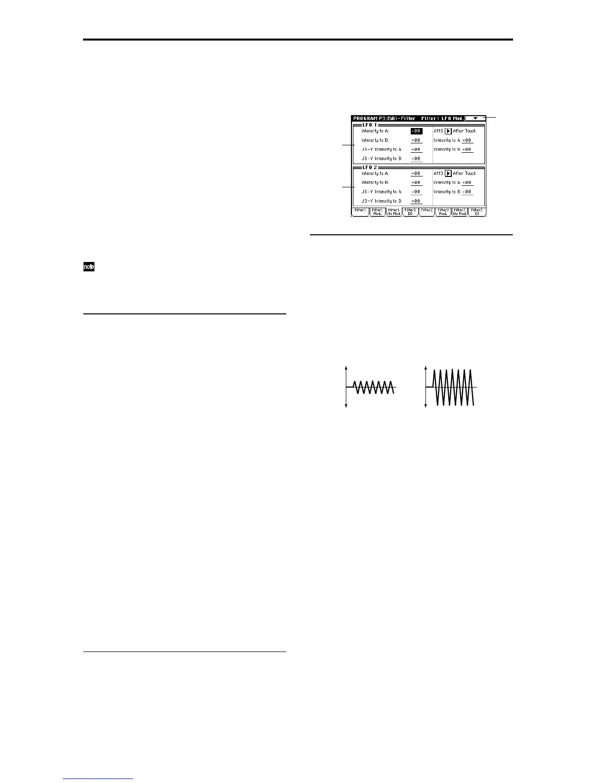
3–3: Filter1 lfo Mod (Filter1 LFO Mod.)
Here you can use the filter 1 LFO to apply cyclic modulation
to the cutoff frequency of filter 1 (for oscillator 1) to create
cyclical changes in tone.
3–3a: LFO 1
Intensity to A [–99…+99]
Specify the depth and direction of the modulation that OSC1
LFO1 (set by “OSC1 LFO1” 5–1) will have on the cutoff fre-
quency of filter 1A.
Negative (–) settings will invert the phase.
Intensity to B [–99…+99]
Specify the depth and direction of the modulation that OSC1
LFO1 will have on the cutoff frequency of filter 1B (
☞“Inten-
sity to A”).
JS–Y Intensity to A [–99…+99]
By moving the joystick in the Y direction (toward yourself),
you can control the depth at which OSC1 LFO1 modulates
the cutoff frequency of filter 1A. This parameter specifies the
depth and direction of the control.
Higher settings of this parameter will produce greater
increases in the effect of OSC1 LFO1 on filter 1 when the joy-
stick is moved toward yourself.
JS–Y Intensity to B [–99…+99]
By moving the joystick in the Y direction (toward yourself),
you can control the depth at which OSC1 LFO1 modulates
the cutoff frequency of filter 1B. This parameter specifies the
depth and direction of the control (
☞“JS-Y Intensity to A”).
AMS (Alternate Modulation Source)
[Off, (PEG, FEG, AEG, KT, EXT)]
Select a source that will control the depth and direction of
cutoff frequency change for both filters 1A and 1B (
☞p.210
“AMS (Alternate Modulation Source) List”).
Intensity to A [–99…+99]
Specify the depth and direction of the effect that “AMS” will
have on filter 1A.
For example if “AMS” is After Touch, higher settings of this
parameter will allow greater change to be applied to OSC1
LFO1 when you apply pressure to the keyboard.
3–3
3–3a
3–3b
Change in cutoff
Low setting High setting