12
Here you can make settings for the filters that will be used
by oscillators 1 and 2. You can select either a 24 dB/octave
low pass filter with resonance, or a series connection of a 12
dB/octave low pass filter and a 12 dB/octave high pass fil-
ter.
When “Oscillator Mode” (1–1a) is set to Single, filter 1 will
be used, and when it is set to Double, filters 1 and 2 will be
used.
When Single is selected, tabs relating to filter 2 cannot be
selected.
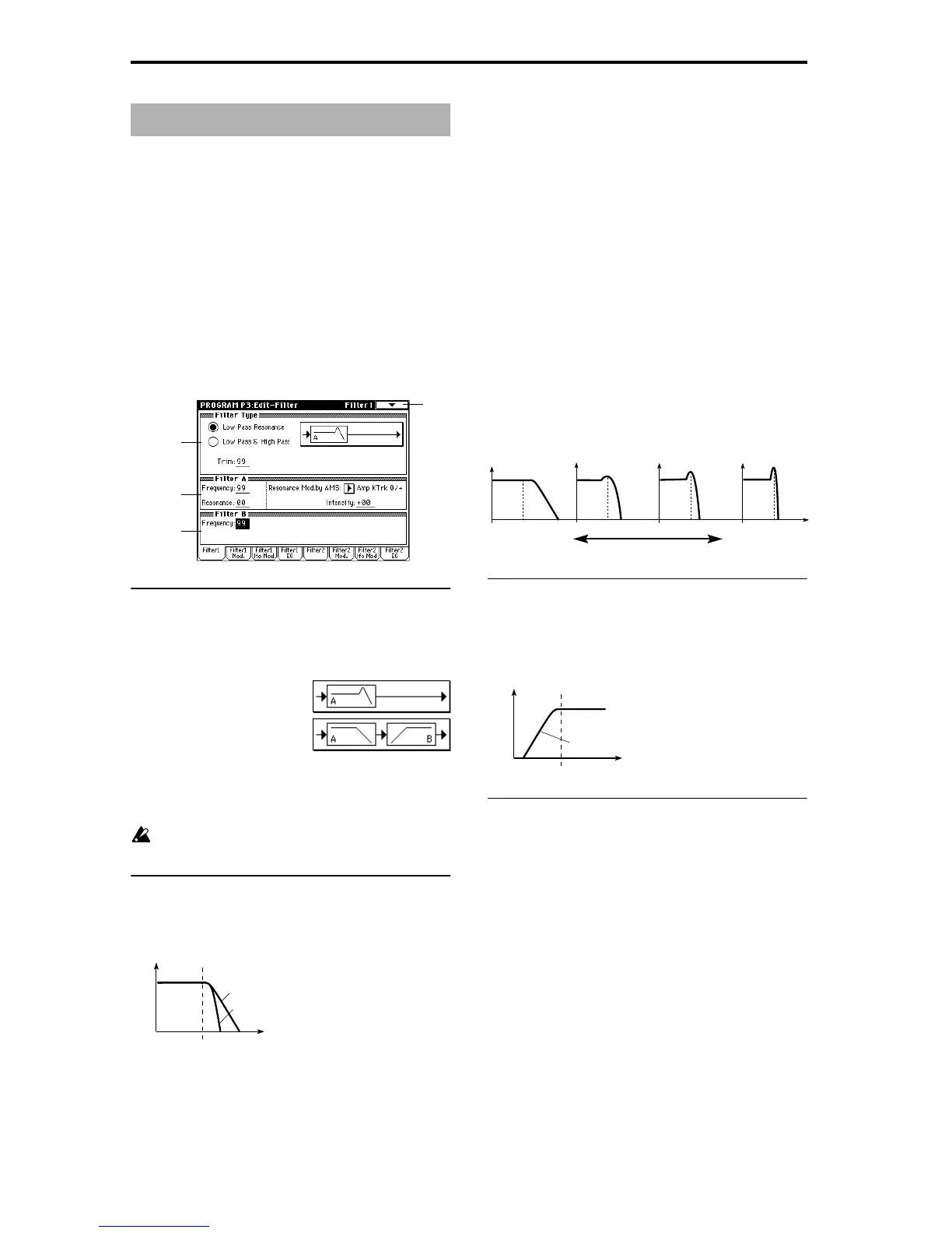
3–1: Filter1
Here you can specify the basic type for filter 1 (used by oscil-
lator 1), and set the cutoff frequency and resonance.
3–1a: Filter Type
Filter Type
[Low Pass Resonance, Low Pass & High Pass]
Select the type for filter 1.
Trim [00…99]
Adjust the level at which the audio signal output from OSC1
is input to filter 1A.
If this value is raised, the sound may be distorted if Res-
onance is set to a high value or when you play a chord.
3–1b: Filter A
Frequency (Cutoff Frequency) [00…99]
Specify the cutoff frequency of filter 1A.
Resonance [00…99]
This emphasizes the overtone components that lie in the
region of the cutoff frequency specified by “Frequency,” pro-
ducing a more distinctive sound. Increasing this value will
produce a stronger effect.
Resonance Mod. by AMS
[Off, (PEG, FEG, AEG, LFO, KT, EXT)]
Select the source that will control the “Resonance” level
(
☞p.210 “AMS (Alternate Modulation Source) List”).
Intensity (AMS Intensity) [–99…+99]
Specify the depth and direction of the effect that “Resonance
Mod. by AMS” will have on the resonance level specified by
“Resonance.”
For example if Velocity has been selected, changes in key-
board velocity will affect the resonance.
With positive (+) values, the resonance will increase as you
play more strongly, and as you play more softly the reso-
nance will approach the level specified by the “Resonance”
setting.
With negative (–) values, the resonance will decrease as you
play more strongly, and as you play more softly the reso-
nance will approach the level specified by the “Resonance”
setting.
The resonance level is determined by adding the “Reso-
nance” and “Intensity (AMS Intensity)” values.
3–1c: Filter B
Frequency (Cutoff Frequency) [00…99]
Specify the cutoff frequency of filter 1B.
This parameter will be displayed when “Type” (3–1a) is set
to Low Pass & High Pass.
▼ 3–1: Page Menu Command
☞ “0–1A: Write Program,” “1–1A: Copy Oscillator,” and “1–
1B: Swap Oscillator.”
Program P3: Edit – Filter
3–1
3–1a
3–1b
3–1c
Low Pass Resonance: 24 dB/octave low
pass filter with resonance
Low Pass & High Pass: 12 dB/octave
low pass filter and 12 dB/octave high pass
filter in series
Frequency
Level
Low Pass
12dB/oct
24dB/oct
This is a filter that cuts the high-
frequency region above the cutoff
frequency.
This is the most common type of filter,
and is used to cut part of the overtone
components, making an originally bright
timbre sound more mellow (darker).
When the “Filter Type” is Low Pass
Resonance, the cutoff will have a
steeper slope.
The effect of resonance
Low Pass
Level
Low resonance value High resonance value
Level
Frequency
High Pass
This filter cuts the low-frequency range that
lies below the cutoff frequency. By cutting
the lower overtones, it lightens the tone.
12dB/oct