Program
P0
P1 P2 P3 P4 P5 P7 P8 P9
15
Intensity to B [–99…+99]
Specify the depth and direction of the effect that “AMS” will
have on filter 1B (
☞“Intensity to A”).
3–3b: LFO 2
Adjust the depth of the cyclic modulation applied by OSC1
LFO2 (set by “OSC1 LFO2” 5–2) to the cutoff frequency of
filters 1A and 1B (
☞“LFO 1” 3–3a).
Intensity to A [–99…+99]
Intensity to B [–99…+99]
JS–Y Intensity to A [–99…+99]
JS–Y Intensity to B [–99…+99]
AMS (Alternate Modulation Source)
[Off, (PEG, FEG, AEG, KT, EXT)]
Intensity to A [–99…+99]
Intensity to B [–99…+99]
▼ 3–3: Page Menu Command
☞ “0–1A: Write Program,” “1–1A: Copy Oscillator,” and “1–
1B: Swap Oscillator.”
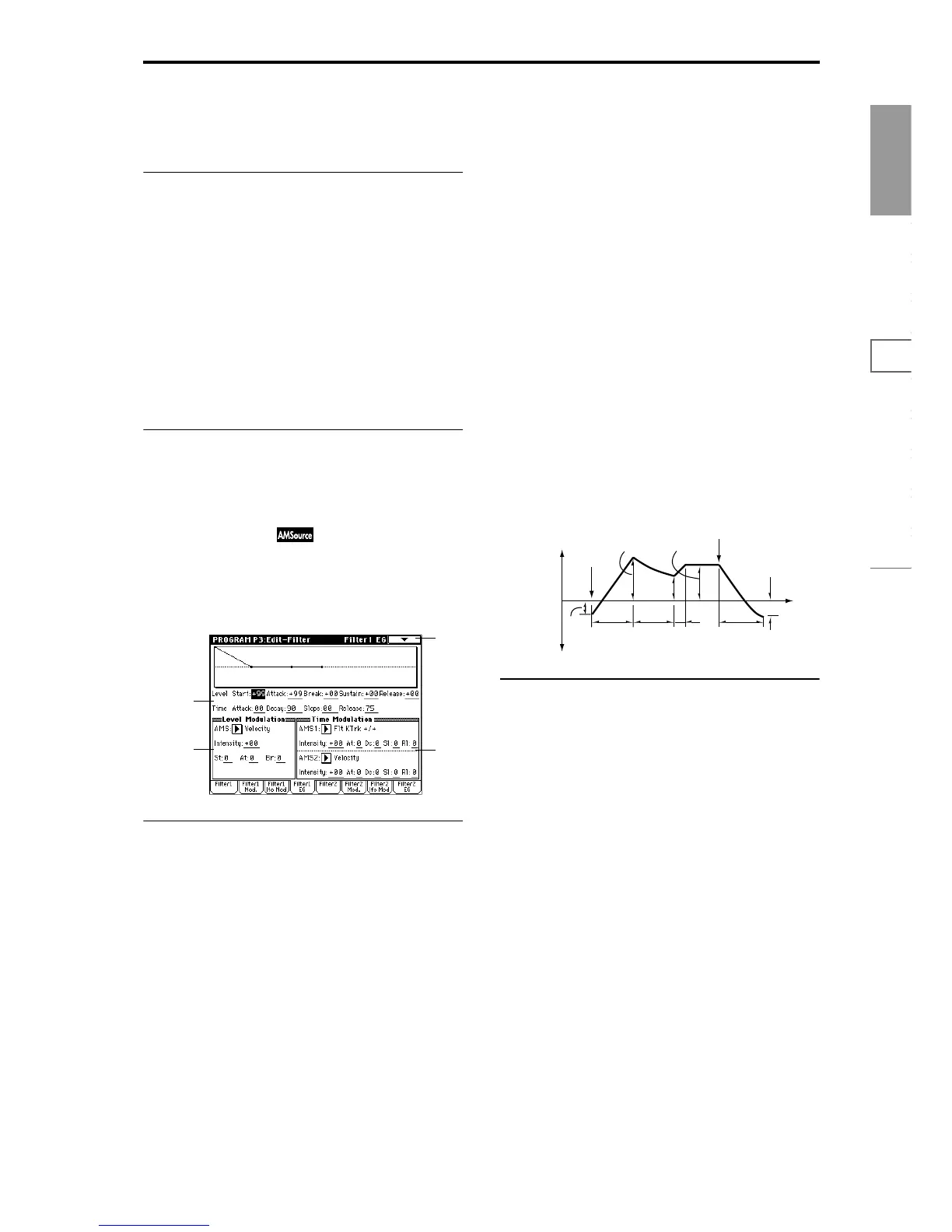
3–4: Filter1 EG
Here you can make settings for the EG that will produce
time-varying changes in the cutoff frequency of filters 1A
and 1B.
The depth of the effect that these settings will have on the
filter 1 cutoff frequency is determined by “Filter EG” (3–2b).
3–4a: Filter1 EG
Specify the time-varying change produced by the filter 1 EG.
Level:
The result will depend on the filter that was selected in “Fil-
ter Type” (3–1a). For example with the Low Pass Resonance
filter, positive (+) values of EG Intensity will cause the tone
to be brightened by positive (+) levels, and darkened by
negative (–) levels.
Start (Start Level) [–99…+99]
Specify the change in cutoff frequency at the time of note-on.
Attack (Attack Level) [–99…+99]
Specify the change in cutoff frequency after the attack time
has elapsed.
Break (Break Point Level) [–99…+99]
Specify the change in cutoff frequency after the decay time
has elapsed.
Sustain (Sustain Level) [–99…+99]
Specify the change in cutoff frequency that will be main-
tained from after the slope time has elapsed until note-off
occurs.
Release (Release Level) [–99…+99]
Specify the change in cutoff frequency that will occur when
the release time has elapsed.
Time:
These parameters specify the time over which each change
will occur.
Attack (Attack Time) [00…99]
Specify the time over which the level will change from note-
on until the attack level is reached.
Decay (Decay Time) [00…99]
Specify the time over which the level will change from the
attack level to the break point level.
Slope (Slope Time) [00…99]
Specify the time over which the level will change after the
decay time has elapsed until the sustain level is reached.
Release (Release Time) [00…99]
Specify the time over which the level will change after note-
on occurs until the release level is reached.
3–4b: Level Modulation
These settings let you use alternate modulation to control
the “Level” parameters of the filter 1 EG.
AMS (Alternate Modulation Source) [Off, (KT, EXT)]
Select the source that will control the “Level” parameters of
the filter 1 EG (
☞p.210 “AMS (Alternate Modulation Source)
List”).
Intensity [–99…+99]
Specify the depth and direction of the effect that “AMS” will
have.
For example if “AMS” is Velocity, and you set “St,” “At”
and “Br” to + and set “Intensity” to a positive (+) value, the
EG levels will rise as you play more strongly. If “Intensity”
is set to a negative (–) values, the EG levels will fall as you
play more strongly.
With a setting of 0, the levels specified by “Filter 1 EG” (3–
4a) will be used.
St (Start Level) [–, 0, +]
Specify the direction in which “AMS” will affect “Start (Start
Level).” When “Intensity” has a positive (+) value, a setting
of + for this parameter will allow “AMS” to raise the EG
level, and a setting of – will allow “AMS” to lower the EG
level. With a setting of 0 there will be no change.
3–4
3–4a
3–4c
3–4b
Note-on
Note-off
Attack
Time
Start
Level
Decay
Time
Release
Time
Release
Level
Attack Level
The specified
cutoff
frequency
Sustain Level
Time
Break
Point
Level
Slope
Time
 Loading...