242
2–B1. Installing an EXB-PCM
A maximum of two EXB-PCM boards can be installed
simultaneously.
If you are installing a single EXB-PCM, it will function
correctly whether installed in either slot. For ease in
installation, you may wish to use EXB-PCM slot 1 first.
Be sure that the AC power cable remains disconnected
until you have completed all steps of removing the
cover, installing the option board/memory, and re-
attaching the cover.
1 Make sure that cover “B” has been removed. (☞“1. Prep-
arations for installation,” “1–B. Removing cover “B” for
the EXB-PCM or DRAM SIMM.”)
2 Remove the EXB-PCM from its packing pouch.
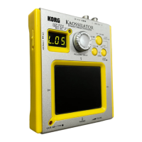
3 Verify the location of the slot into which you wish to
install the EXB-PCM. With the rear panel of the TRITON
facing toward you, the back two rows are the EXB-PCM
slots.
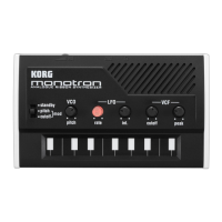
4 The notched side of the EXB-PCM is PIN 1. Install the
EXB-PCM with its PIN 1 side aligned with the PIN 1
mark ( ) of the slot.
The EXB-PCM slots and the DRAM SIMM slots are
shaped identically. Be careful not to install a board in
the wrong slot.
5 At a slant, press the EXB-PCM firmly all the way into the
slot, and raise it to the vertical position until the catches
of the slot click into the locking holes of the EXB-PCM.
When doing so, pressing the catches of the slot apart to
the left and right will help the board go in smoothly.
6 Reversing the procedure by which you removed cover
“B,” re-attach the cover.
7 When all steps have been completed, turn on the power
and make sure that the EXB-PCM has been installed cor-
rectly. (
☞“Checking after installation”)
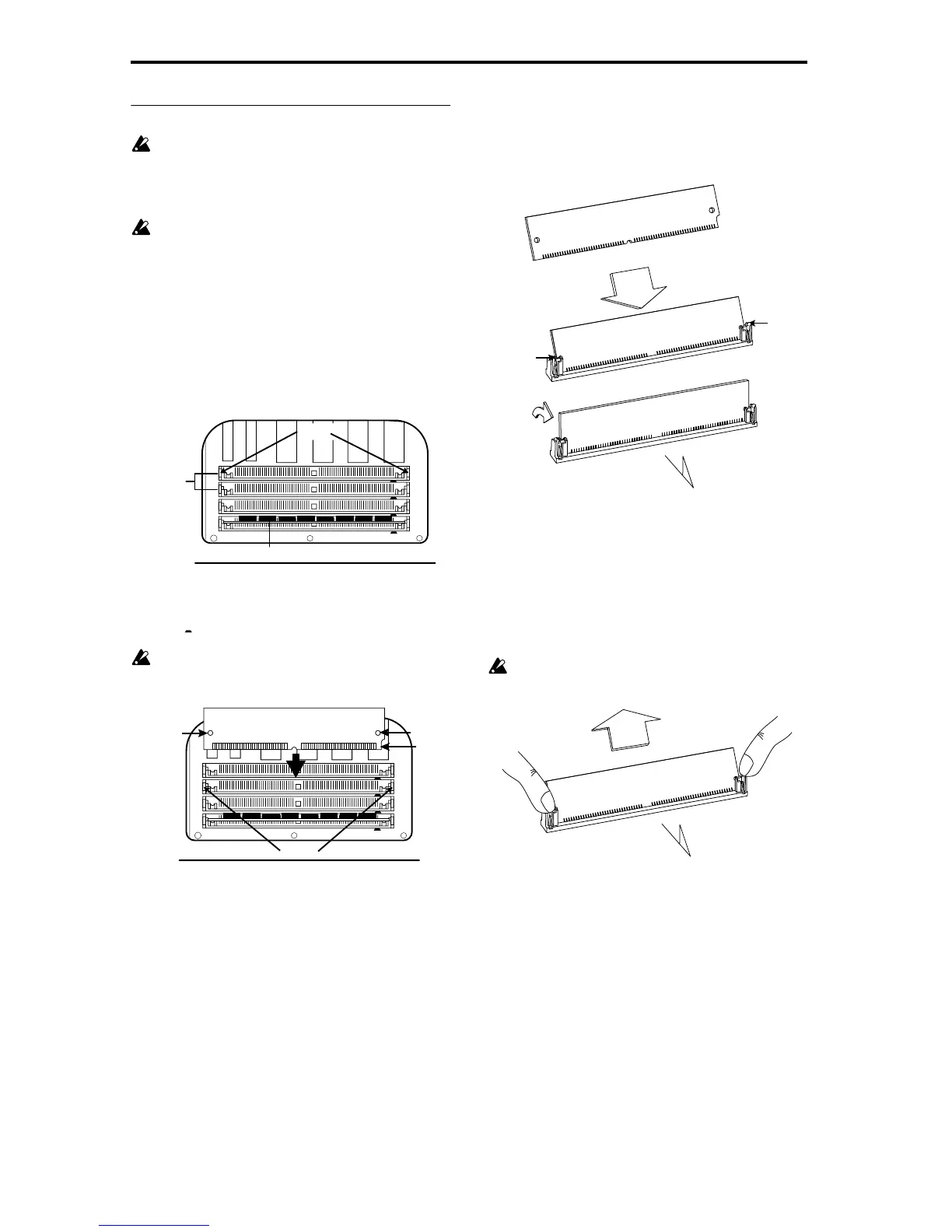
Removing an EXB-PCM
Spread the catches of the slot apart to the left and right, and
(after removing the stoppers from the catches) tilt the EXB-
PCM and pull it out.
When you spread the catches of the slot apart, the EXB-
PCM may pop out vigorously and fall into an opening
(inside the instrument). Please be careful.
EXB-PCM
Slot2
EXB-PCM
Slot1
SIMM
Slot2
SIMM
Slot1
EXB-PCM
slots
Catches
Rear panel
Factory-installed DRAM SIMM
EXB-PCM
Slot2
EXB-PCM
Slot1
SIMM
Slot2
SIMM
Slot1
1PIN
72PIN
Rear panel
Rear side of the EXB-PCM
Catches
Locking
hole
Locking
hole
Notch
Rear panel
Rear side of EXB-PCM
Rear side of EXB-PCM
Rear side of EXB-PCM
Catch
Catch
Press in at a slant
Raise to vertical
Rear panel
Rear side of EXB-PCM
 Loading...