L-Gate User Manual 125 LOYTEC
Version 3.2 LOYTEC electronics GmbH
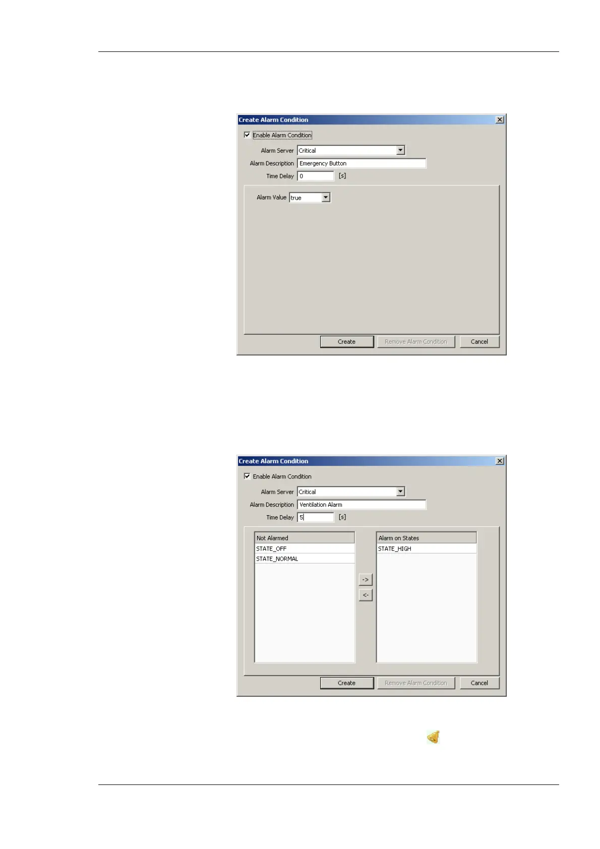
data point is used. Enter a Time Delay, after which the condition is evaluated. Select
the Alarm Value which triggers the alarm.
Figure 106: Alarm Condition for a Binary Data Point.
5. For a multi-state data point the dialog as shown in Figure 107 appears. Select the
Alarm Server. Optionally, enter an Alarm Description. If left empty, the description
of the data point is used. Enter a Time Delay, after which the condition is evaluated.
Select the Alarm States, which triggers the alarm, by clicking the arrow buttons.
Figure 107: Alarm Condition for a Multi-State Data Point.
6. Click on Create. In the alarm column, the alarm sign will be added for those data
points, that have an alarm condition.