EasyManua.ls Logo

LSIS sv-ip5a User Manual

LSIS sv-ip5a
210 pages
To Next Page IconTo Next Page
To Previous Page IconTo Previous Page
Page #106 background imageLoading...
Page #106 background image
Chapter 6 - Parameter Description [FU2]
6-24
6.3 Function 2 Group [FU2]
FU2-00: Jump to desired code #
Jumping directly to any parameter code can be
accomplished by entering the desired code number.
This code is available only with LCD keypad.
FU2-01: Last trip 1
FU2-02: Last trip 2
FU2-03: Last trip 3
FU2-04: Last trip 4
FU2-05: Last trip 5
FU2-06: Erase Trips
ā–”
ā–”
ā–”
This code displays up to five previous fault (trip)
status of the inverter. Use the PROG,
ā–² and ā–¼ key
before pressing the RESET key to check the fault
content(s) such as output frequency, output current,
and whether the inverter was accelerating,
decelerating, or in constant speed at the time of the
fault occurred. Press the ENT key to exit.
FU2-83 [Last Trip Time] is the time elapsed after last
trip occurs. User can count the last trip time from this
value.
Note: There are WDOG error, EEP error, and
ADC Offset for the inverter Hardware Fault, and
the inverter will not reset when H/W fault occurs.
Repair the fault before turning on the power.
This function erases all fault histories of FU2-01 to
FU-05 from the memory.
However, FU2-83 [Last Trip Time] cannot be reset.
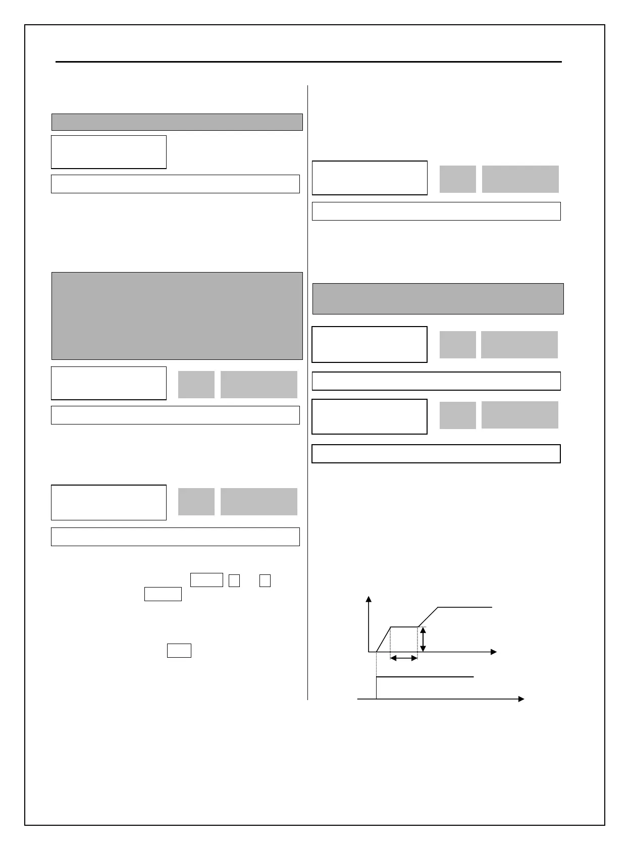
FU2-07: Dwell Time
FU2-08: Dwell Frequency
Note: If the dwell time is set at ā€˜0’, this function is
not available.
Note: Do not set the Dwell frequency above
frequency command. Otherwise, it may lead to
operation fault.
Note: this function is disabled in Sensorless
control.
FU2
ā–ŗ
Jump code
00 1
Factory Default: 1 1
FU2
ā–ŗ
Last trip-1
01 None
nOn 01
Factory Default: None nOn
FU2
ā–ŗ
Last trip-5
05 None
nOn 05
Factory Default: None nOn
FU2
ā–ŗ
Erase trips
06 --- No ---
0 06
Factory Default: No 0
FU2
ā–ŗ
Dwell freq
08 5.00 Hz
5.00
07
Factory Default: 5.00 Hz 5.00
FU2
ā–ŗ
Dwell time
07 0.0 sec
0.0
08
Factory Default: 0.0 sec 0.0
FU2-07
FU2-08
Time
RUN
Output freq.

Table of Contents

Question and Answer IconNeed help?

Do you have a question about the LSIS sv-ip5a and is the answer not in the manual?

LSIS sv-ip5a Specifications

General IconGeneral
BrandLSIS
Modelsv-ip5a
CategoryController
LanguageEnglish

Summary

SAFETY INSTRUCTIONS

Safety Symbols and Warnings

Explains DANGER, WARNING, and CAUTION symbols for safety.

OPERATING PRECAUTIONS

Handling and Installation

Guidelines for safely handling and installing the inverter.

Wiring Precautions

General precautions to follow before and during inverter wiring procedures.

CHAPTER 3 - INSTALLATION

Installation Precautions

Key safety and environmental guidelines for installing the inverter.

Basic Wiring

Describes the basic wiring diagram for 5.5-30kW inverters.

Wiring Power Terminals

Details wiring precautions and terminal sizes for power connections.

Control Circuit Wiring

Details wiring for control circuit terminals, including digital and analog inputs/outputs.

Grounding

Essential guidelines for proper grounding to ensure safety and prevent electrical shock.

CHAPTER 4 - OPERATION

Programming Keypads and LCD Display

Details on the LCD keypad, its functions, and parameter setting procedures.

Operating Examples

Practical demonstrations of various inverter operation modes, including keypad and terminal control.

CHAPTER 6 - PARAMETER DESCRIPTION

CHAPTER 7 - TROUBLESHOOTING & MAINTENANCE

Fault Display

Lists inverter faults, protective functions, and causes for each error displayed on the keypad.

Fault Remedy

Provides solutions and remedies for various inverter fault conditions and their causes.

Troubleshooting

Common troubleshooting steps and checking points for operational issues like motor rotation or speed differences.

How to Check Power Components

Instructions for checking diode and IGBT modules for proper function using a tester.

Maintenance

Guidelines for routine, periodic, and dielectric testing to ensure proper inverter maintenance.

CHAPTER 9 - RS485 COMMUNICATION

Troubleshooting

Troubleshooting guide for common RS485 communication errors and their solutions.

Related product manuals